
Replacement
1. Loosen the hub nut at the end of the drive shaft and the wheel bolts (the car is on the ground).
2. Raise and support the front of the vehicle. Remove the wheel.
3. Remove the six bolts securing the inner end of the drive shaft to the axle shaft flange using a special wrench (bolts have heads with slotted 12-sided turnkey sockets "star" size 8 mm). Disconnect the drive shaft from the flange and lower the inner end of the shaft.
4. Remove the hub nut and thrust washer from the outer end of the drive shaft, then knock the shaft out of the wheel hub using a copper or nylon hammer.
5. Remove the drive shaft from under the vehicle.
6. Installation of a shaft is carried out upside-down.
7. Tighten the bolts from the shaft to the axle shaft flange with the torque specified in section "Technical data".
8. Finally tighten the hub nut after the vehicle is on the ground. Be sure to install a NEW nut and tighten it to 24.0 kNm.
Replacement of the outer constant velocity joint
Excessive play in the constant velocity joint becomes noticeable with changes in load, which usually manifests itself in the form of characteristic clicks during sharp acceleration or deceleration, especially if the front wheels are turned to the extreme position. In case of excessive wear, replace the joint.
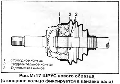
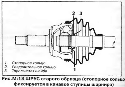
The outer hinge can be one of two types - depending on this, different methods of removing the hinge are used. On early models, the CV joint is secured with a large retaining ring that locks into the inner groove of the pivot hub (pic. M:18). Retaining ring is visible from the side of the drive shaft when the hinge cover is removed (pic. M:15). For later (from December 1979) models, new-style hinges are installed, which are fastened with a retaining ring fixed in a groove at the end of the shaft (pic. M:17).
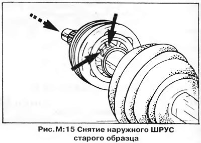
To remove the old style joint, remove the cover from it and slide the cover along the shaft, then spread the ends of the retaining ring with needle-nosed pliers and at the same time apply a side blow to the splined shank of the joint (pic. M:15) - in this case, the retaining ring will come out of the groove of the shaft and allow you to remove the hinge.
The hinge of the new model is removed with a simple blow of a soft (aluminum) hammer; first you need to remove the hinge cover.
Stuff the new joint with 90 g of molybdenum grease (usually lubrication is included in the delivery of the hinge).
Slide the joint boot and clamps onto the drive shaft and install the new joint onto the shaft in the reverse order of removal. Anyway (even when installing the old hinge) install a new circlip into the pivot hub (old style hinge) or into a shaft groove (new design hinge). Make sure that the spacer ring and Belleville washer are installed correctly (fig. M: 17 and M: 18). Press the joint onto the shaft so that the retaining ring fits into the groove. Secure the hinge boot with new clamps
Replacement of the internal constant velocity joint
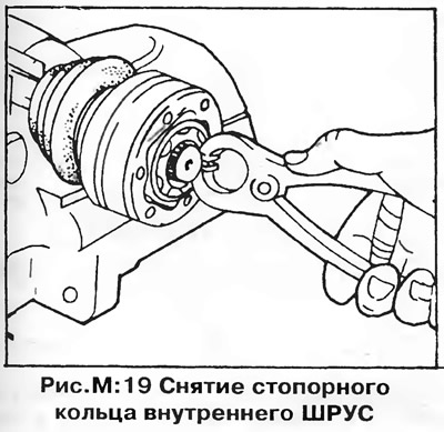
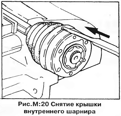
Remove the retaining ring from the end of the inner hinge (pic. M:19), then knock off the hinge cover (pic. M:20) and, supporting the hinge, knock the shaft out of it with a wooden or brass drift.
Pack 90 g of molybdenum grease into the new joint - 45 g on each side of the joint (usually lubrication is included in the delivery of the hinge).
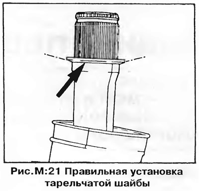
Put on a power shaft a cover and a cover of the hinge. Make sure the Belleville Washer is in the correct position (pic. M:21). Press the new joint onto the shaft using a mandrel of suitable diameter, which must rest only on the joint hub. Install retaining ring (necessarily new) groove with circlip pliers. Press on the cover from the outside of the hinge.

Visitor comments