Minus "to mass"
Electric current can only flow in a closed circle. When you press the switch at home, the light comes on. The same thing happens in the car, only in it the electric current coming from the battery or generator returns through the corresponding consumers back to the battery or generator
To a multitude of current consumers in "Volkswagen" 2 cables connected. But only one is directed back to the battery or alternator. This is visible on electrical diagrams. The second wire, in most cases, is connected to the metal of the body after a few centimeters. In this case, the property is used: the metal parts of the body and the engine or gearbox can also conduct electric current. In automotive electrical engineering, they are called "weight". They provide the reverse flow of electric current to the negative pole of the battery. Note: minus k "mass".
Instruction. If any incandescent lamp or indicator device does not function as it should, often the reason is a lack of connection "to ground".
Standard Pointer
The interlacing of colored cables in a car is very well ordered, as many parts of the electrical equipment are standardized. The numbers available on various structural parts and cable connections, as well as on wiring diagrams, have the same meaning in all German and some foreign cars.
Terminal 15. Only when the ignition key is in the first position, terminal 1.5 receives current from the ignition switch. In addition to the additional glowing system, those current consumers that must receive current during the operation of the machine receive power. Cables at standard terminals 1.5 have a black sheath, sometimes with additional colored stripes for certain current consumers.
Terminal X This is the designation given by the company "Volkswagen" connections that only conduct electricity when the ignition is on. but not when the ignition switch is in position "Start" ("Anlassen"). The color of the cable is black-yellow.
Terminal 30. Continuously receives electrical current from the positive terminal of the battery or from the alternator when the engine is running. This can lead to a short circuit or sparking if the tool is not handled carefully. if the negative battery cable has not been removed. These cables always conduct electricity and in most cases have a red sheath, sometimes with additional colored stripes.
Terminal 49 designed for emergency light signaling and direction indicators.
Terminal 53 intended for glass cleaner. In most cases, the wiring is green or green with stripes.
Terminal 56 designed to supply voltage for low beam operation; cables are yellow or yellow-black. Terminal 56 is also for high beam; wires are white and white-black.
Terminal 58 for front parking lights, as well as for rear lamps and rear number plate lamps. The main color of the cable sheath of the series with additional colored stripes.
Terminal 31 - this is a connection clamp "to ground". With this terminal, the current consumer must be connected to "weight" car. so that the circuit is closed. Corresponding cables have brown sheaths.
Wires
You always see only the ends of individual colored cables, as they are covered with black insulation. If you do the installation yourself, it is important to know that the cable cross-section is selected depending on the current demand of the respective consumer. A cable with a cross section of 0.5 mm is enough for a control light2, the starter needs a wire with a cross section of 16 mm2. A cable that is too thin will heat up and the voltage will drop. Then, instead of the desired 12 V, the headlight has only 10 or 9.5 V, the light becomes dim.
Central part of electrical equipment
Without exception, all electrical wires are combined into certain lines. They come from the so-called central part of the electrical equipment (relay and fuse box), located at the bottom of the car, near the driver's feet. There are fuses and relays. We will describe the operation and mounting arrangement of various relays and control devices in the section "Relays and control devices", chapter "Devices".
If during troubleshooting it is found that the wires, the corresponding fuse or relay are not damaged, then a defect in the central part of the electrical equipment is possible. Typical malfunctions: bad contacts or failure due to heating. In addition, some connection may be open. For repair, the central part of the electrical equipment must be disassembled.
Before you yourself approach the central part of the electrical equipment, you should use a certain wiring diagram to find out whether it is possible to bridge an open place. But be careful, do not connect additional consumers to another current circuit!

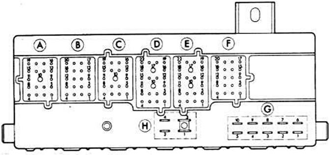
Central part of electrical equipment (release before July 1982). The letters indicate the connected multi-pin plugs. Contacts G are adjacent to G1 and G6 - terminal 30 (fuse 15); G2 - terminal 53c; G3 - terminal 15; G4 - terminal 58b (fuse 12); G5 - terminal 61; G7 - terminal X; G8 - terminal 56a; G9 - oil pressure; G10 - terminal 56; H-contacts: all terminals 30.

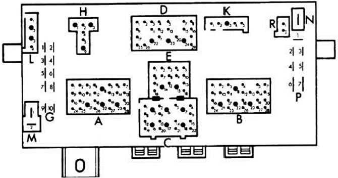
Central part of electrical equipment (release after August 1982). Letters designate G1 and G3 terminal X; G2 and G5 - terminal 15; G4 - terminal 61; G6 - oil pressure 0.3 bar; G7 - terminal 56; G8 - terminal 58; G9 - terminal 58, G10 - terminal T, washer pump; P1-P7 terminal 30. The remaining letters indicate multi-pin plugs.

Visitor comments