A simple switching relay is used for powerful current consumers. If electric current is directed through long wires through appropriate switches, there is a voltage loss. In addition, the contacts of the switches are heavily loaded due to the high electric current. In the connection scheme with a relay, a switch is used, which is intended only for a small switching current and switches on the relay, and the relay switches on the consumer.
Some relays may perform additional functions. So, for example, the turn relay gives impulses. The wiper time relay controls the process of washing and cleaning the windows.
Control devices have more or less extensive electronic circuits to perform certain functions. Sometimes an additional relay is installed. The control unit for the switching indicator is shown here as examples (tooling according to the formula E) or control unit for automatic pre-glow system (release after August 1977).

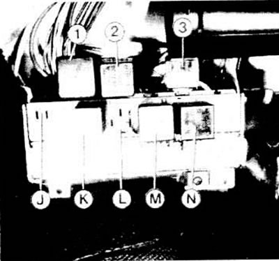
Connectors of the central part of the electrical equipment manufactured before July 1982: 1 - free panel; K - unloading relay for X-contacts, first relay for heating arrow; L - free panel, formerly radiator fan relay; M - wiper time relay; N - flashing alarm relay; 1 - pre-glow relay; 2 - rear window cleaner relay; 3 - additional block with fuses
Relay operation
When a certain consumer is switched on, a current circuit is closed in the switching relay from terminal 85 to terminal 86.
Due to this, the magnetic coil attracts the contact, overcoming the force of the spring: this closes the operating current circuit.
The operating current is connected to terminal 30 of the relay; current from there (with closed switch contacts) via terminal 87 goes to current consumers.
The relay works somewhat differently for two-tone signals. Read about it in the next text.

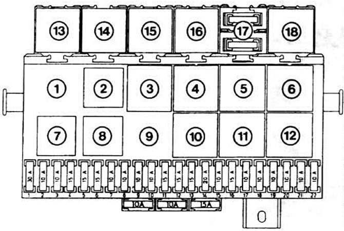
The central part of the electrical equipment manufactured after August 1982: 1 - free space; 2 - pre-glow relay; 3 - free space; 4 - control device for switching indicator (formula E equipment); 5 - free space; 6 - relay for a two-tone sound signal; 7 - fog lamp relay; 8 - unloading relay for X-contacts; 9 - free space; 10 - wiper time relay; 11 - rear window wiper relay; 12 - turn relay.
Relays are located in the upper row according to special equipment, for example, for the headlight cleaning system. Position "17" indicates an additional fuse box for the fog lights and rear fog light.
Relay Troubleshooting
Terminal 30 is always energized. For control, it is necessary to partially pull out the relay; touch test lamp needle to terminal 30
Remove relay. Connect terminal 86 to positive" battery, and terminal 85 - with "weight". The magnetic coil should attract the relay contact (sound is heard), otherwise the relay is defective.
Pull out partially the relay of the two-tone signaling device. Terminal 86 should have voltage when the ignition is on.
When you press the horn contact, the magnetic coil should attract the relay contact (a distinct sound is heard) and close the connection "to mass" (grounding) to sound signals. Terminal 30 is connected here "with mass", in contrast to the usual scheme.
Remove the relay; bridge the contacts of terminals 87 and 30 with a strong, insulated piece of wire in the place where the relay is located.
Turn on the ignition. If a signal now sounds, then the relay is defective, if all wire connections have been checked and found to be in good condition.
What to do if the relay has a defect
Remove the relay from the connector.
On the relay connector, connect terminals 30 and 87 with a paper clip or a small piece of wire. As a result, the corresponding consumer is constantly supplied with electric current.
To disconnect, remove the wire, since the corresponding switch is disabled in this case.
Cigarette lighter
The cigarette lighter receives current for a long time through the corresponding fuse. If it doesn't work despite a good fuse, the filament insert is loose or burned out.

Visitor comments