Disconnect the wires from the battery.
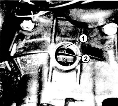
In the diesel model produced in November 1978, turn the piston of the 1st cylinder to the position of 76 degrees before dead center "FROM". In the viewing window, the point of the arrow is against a small recess in the flywheel (see illustration).

For diesel model "Golf" release before November 1978 to disconnect the engine from the gearbox mark 76 degrees in front of OT on the flywheel (2) should be located opposite the arrow in the viewing window of the cap (1) clutch The inspection window is usually closed with a plastic cover.
Lay a 30-50 diameter pipe above the engine compartment transversely through the wooden spacers on the mounting edges of the fenders, but not directly on the fenders. Flatten the pipe edges to prevent twisting. Suspend the engine from the pipe while the drive mechanism supports are disconnected.
Pull the chain or cable through both eyelets of the cylinder head or fasten it to the pipe.
Remove the clutch cable near the clutch lever.
Remove the left transmission support.
Remove the tachometer shaft from the gearbox (see chapter "Devices") and close the hole so that no oil flows out when the gearbox is removed.
Disconnect the electrical wires from the reversing light switch, and (if necessary) electrical wires to the switch indication board.
Disconnect the wire connecting "with mass" gearbox.
Remove starter (see chapter "Starter") and hang it so that it does not pull the corresponding wires.
Disconnect axle shafts from gearbox. Connect both shafts with wire and hang.
Remove switch rods. With a four-speed gearbox, disconnect the shift unit from the shaft; Remove the swing arm from the support rod or support column.
In a five-speed gearbox, remove the connecting rod safety spring, and the latter near the control lever.
Move forward from the spherical pins the left plastic head of the rear control rod and both heads of the control rod.
Preliminary use a screwdriver to lift the plastic bracket of the plastic head.
Disconnect the torque rod from the gearbox and from the body (absorbing torsional forces) front.
Remove the rear support from the gearbox and body.
Release the connecting screws at the top between engine and gearbox.
Unscrew the bolt at the hatch on the engine side; remove hatch.
Unscrew the hexagon head bolt or nut under the right axle shaft flange (on older models).
Raise the gearbox slightly with a jack, place a block of wood, or otherwise securely fix it.
Two people need to lift the box.
Use a powerful screwdriver to move the gearbox away from the mounting bushings; take it off.
Lubricate the gearbox input shaft with a small amount of paste before installing "Moli".
When installing the gearbox, pay attention: the clutch must be correctly positioned at the engine.
Remove the tension to install the engine and gearbox mounts.
Adjust clutch free play (see chapter "Clutch").
Re-adjust the switching unit if necessary.
Tightening torques for threaded connections
| Structural parts | Nm |
| Gearbox to engine | 45 (M 10) 75 (M 12) |
| Cardan shafts to gearbox | 45 |
| Starter and gearbox | 25 |
| Suspensions at the gearbox | 40 |
| Hangers on the body | 40 |
| Switching unit to switching shaft | 15 |

Visitor comments