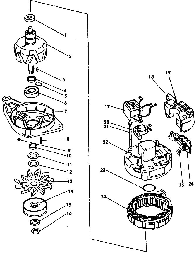
Unscrewing nut 1 (pic. 444) from the rotor shaft, hold the pulley as described above.

Pic. 444. MOTOROLA generator components (45 A): 1 - bearing; 2 - rotor; 3 - key; 4 - spacer sleeve; 5 - plate with a threaded hole; 6 - front bearing; 7 - front cover; 8 - bolt; 9 - nut; 10, 15 - rings; 11, 12 - washers (gaskets); 13 - impeller; 14 - pulley; 16 - nut (35 Nm); 17 - voltage regulator; 18 - connector spring; 19 - cover of the rectifier unit; 20 - brush holder; 21 - tightening bolt; 22 - stator housing; 23 - gasket; 24 - stator; 25 - insulating sleeve; 26 - rectifier block
Remove the pulley, fan, washer and spacer.
On the back of the cover, release the connector spring and remove the cover.
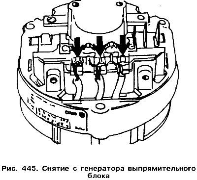
Unsolder the diode wires and remove the rectifier unit. Soldering iron power should not exceed 300 W (pic. 445).

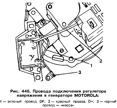
Remove the voltage regulator mount and move it aside. Designate the wires placed under it (pic. 446) and disconnect them from the clamps.

Unscrew the brush holders and remove them. The length of the protruding part of the brushes must be at least 5.0 mm.
Mark the relative position of the front cover and the stator housing. Unscrew the tie bolts and separate them, helping yourself with two screwdrivers. The stator will remain in the housing.
Remove the rear rotor bearing using a two-jaw puller.
Unscrew the bearing mounting plate from the front cover and remove the bearing.
Assemble the generator in reverse order.

Visitor comments