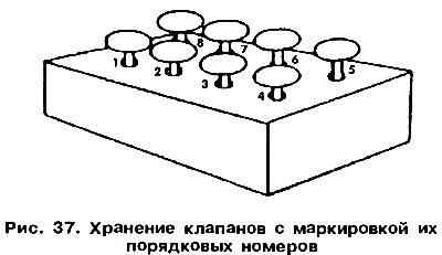
During disassembly, it must be remembered that all separable components should be marked before they are removed. This will allow you to install them in their original places if they are used again. This is especially true for pistons, valves, bearing shells. Removed parts carefully set aside to exclude the possibility of their replacement. For marking, you can not use scribers and center punches. Paint works best for this. It is good to keep the valves inserted into the bottom of an inverted cardboard box, on which their serial numbers are written (pic. 37). Many engine parts are made of aluminum alloys. If it is necessary to use a hammer to remove such parts, then it can only be rubber, plastic or wooden.

If you do not have a special mounting stand, then you can use wooden goats, on which you should install the removed engine. The removed cylinder head can be secured in a vise to a metal plate screwed to the intake manifold bolts. Below is the usual order of disassembly of the engine. Details of the disassembly of individual engine components should be sought further in the relevant sections. The cylinder head, oil pump and camshaft drive belt can be removed from the engine without removing it from the vehicle. Carry out engine disassembly in the following order.
Remove accessories from engine (ignition system components, carburetor with intake manifold, injection unit, exhaust manifold, etc.).
Remove the toothed belt cover and remove the belt. Remove the toothed pulley from the crankshaft.
Remove the flywheel from the crankshaft and the cover under it.
Attention! Before removing the flywheel, mark the relative position of the flywheel and the crankshaft flange.
Remove the water pump and oil filter.
Remove the oil dipstick.
Remove the valve cover and remove the gasket.
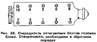
Remove the block head. Loosen the fixing screws gradually. The sequence of unscrewing the bolts is shown in fig. 38. When working, it is necessary to use a wrench with end caps, otherwise the bolt heads may be damaged.

Remove the O-ring cover from the front of the block head.
Turn the engine over and remove the oil pan. Remove the pan gasket.
Remove the oil pump according to section.
By moving the crankshaft to the extreme (e.g. left) position with a feeler gauge, measure the end play and record the reading.
Paint the cylinder numbers on the connecting rod bearing caps and remove them. When loosening the cap bolts, the piston must be at BDC. Remove the pistons together with the connecting rods from the cylinders upwards. The covers, together with the liners, must be subsequently installed in their original places.
Remove the crankshaft (see section). Main bearing caps are numbered («1» from the side of the pulley and «5» flywheel side). At the middle support there are half rings that serve to adjust the axial play of the crankshaft. Remove the bushings and half rings, marking them in order.
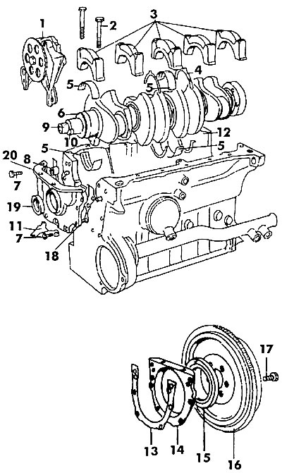
When disassembling the engine, use fig. 39, which shows the main components and parts installed in the cylinder block.

Pic. 39. Engine block: 1 - oil pump, 2 - main bearing cap bolt (65 Nm), 3 - main bearing caps, 4 - thrust half ring, 5 - bushing, 6 - oil pump drive sprocket, 7 - bolt, 8 - bushing, 9 - crankshaft, 10 - groove, 11 - ignition setting reference mark, 12 - block cylinders, 13 - gasket, 14 - rear cover, 15 - rear oil seal, 16 - flywheel, 17 - bolt, 18 - gasket, 19 - front oil seal, 20 - front cover

Visitor comments