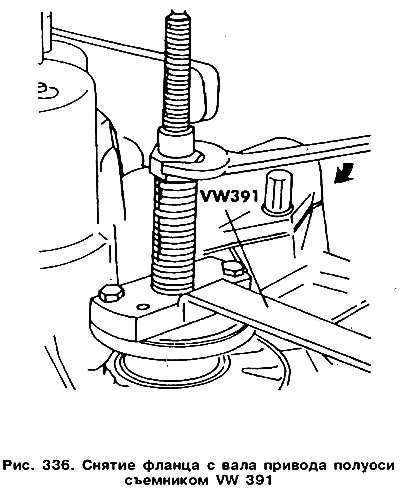
Disconnect from the final drive the drive shaft flange from the gearbox housing on the clutch side. To do this, remove the plastic lining and the retaining spring ring that fixes the flange on the shaft from the flange: Remove the gasket located under it. Screw the special puller with two bolts to the flange and, tightening the puller nut, remove the flange from the shaft (pic. 336).
Unscrew the four bolts securing the rear crankcase cover and remove the cover together with the gasket.
Remove both locks of the clutch lever shaft located inside the crankcase and remove the shaft from the lever and from the crankcase.
Remove the clutch thrust bearing, guide bush, and clutch lever return spring.
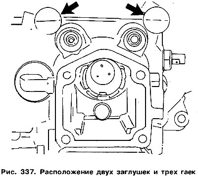
Pry off both plugs with a screwdriver (arrows in fig. 337) and take them out. Remove three nuts.
Install the gearbox so that the main gear is on the left side. From the right wall of the crankcase, unscrew the bolt holding the gear selector rod. To do this, you need a sawn candle key. If the indicator of the selected gear and fuel consumption is installed, unscrew the bolt 2 (see fig. 334), remove the oil deflector and the large spring.
In front of the crankcase, remove the bolt blocking the reverse gear.
Unscrew the reversing light switch or switch 1 (see fig. 334). Remove all bolts connecting both parts of the crankcase.
Remove the clutch fork.
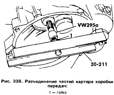
Disconnect the top of the crankcase from the bottom. To do this, you need to use a special bracket 30-211 and a bushing VW 295a (pic. 338). The upper part of the bracket is screwed to the upper wall of the crankcase (above the main shaft). Screw on the nut 1 of the central bolt of the puller until both parts of the crankcase are separated. Remove the shim from the top of the bearing. The lower part of the bracket 30-211 supports the input shaft from below.
Attention! If one of the gearbox housing halves or the input shaft is to be replaced, it is necessary to determine the thickness of the input shaft bearing shim.
The dismantling of the primary and secondary shafts is carried out as follows:
- Remove two retaining rings (one from the crankcase, the other from the side of the bearing race) and remove the fork shaft. Remove the fork set from the shaft.
- Remove the 4th gear circlip from the output shaft.
- Remove the input shaft along with the 4th gear removed from the output shaft. Dismantle the output shaft as described below. Remove the gear set before removing the shaft from the bearing race.
- Remove the 4th gear from the output shaft. Note that the pinion on the gear is pointing up.
- Remove the second circlip located under the gear. This ring can have a different thickness and serves to adjust the axial play of the 3rd gear gear.
- Remove the 3rd gear. Pay attention to the fact that the ledge on the gear is directed downward, i.e., towards the 2nd gear gear.
- Remove the 2nd gear gear together with the needle bearing.
- Remove the reverse gear together with the shaft. You can use a rubber mallet to knock the shaft out of the housing.
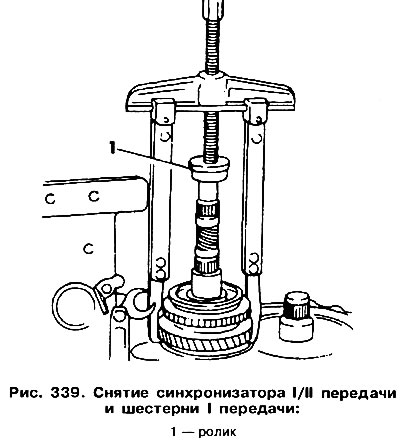
- With a long puller with two arms and a roller 1 (pic. 339) remove the 1st gear gear and the 1st/2nd gear synchronizer from the shaft.
- Remove the gear needle bearing and spring washer underneath.
- After unscrewing the four bolts securing the bearing cover to the housing, remove the cover.
- Remove the output shaft from the housing. Dismantling of a secondary shaft can be made, being guided by fig. 340.
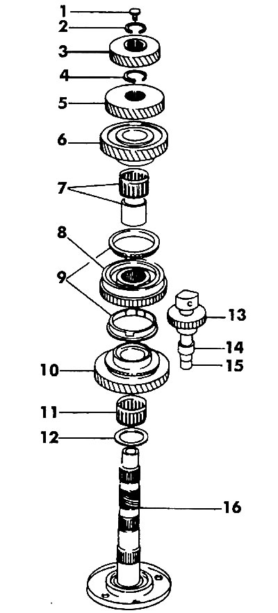
Pic. 340. Secondary shaft: 1 - needle bearing limiter; 2, 4 - retaining rings; 3 - gear IV gear; 5 - gear III gear; 6 - gear 11 gears; 7 - needle bearing; 8 - synchronizer of I / II gears; 9 - synchronizer blocking ring; 10 - gear 1st gear; 11 - needle bearing; 12 - spring washer; 13 - reverse gear gear; 14 - spacer sleeve (not in 1983 model); 15 - reverse gear shaft; 16 - secondary shaft '
Dismantling of the main gear must be carried out when removing the drive shaft (see fig. 336) and differential. The primary and secondary shafts must be dismantled beforehand. Knots and details of the main transfer are shown in fig. 341. Previously used retaining rings of the pin of satellites are replaced by elongated rivets, which also serve to fasten the ring gear of the driven gear of the final drive (pic. 342).
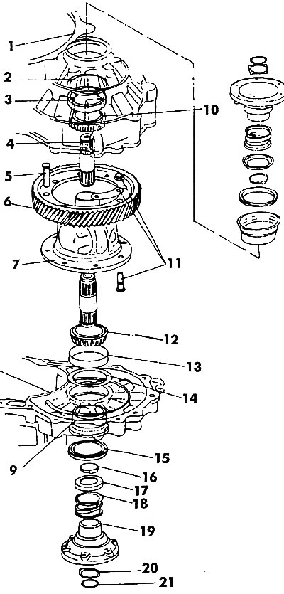
Pic. 341. Main gear and differential: 1 - gearbox housing from the clutch side; 2 - adjusting gasket; 3 - bearing race; 4 - drive shaft; 5 - rivet (not installed after repair); 6 - gear. the crown of the driven gear of the main gear; 7 - differential case; 8 - gearbox housing; 9 - thin-walled sleeve; 10 - tapered bearing; 11 - bolt, nut (70 Nm); 12 - tapered bearing; 13 - bearing race; 14 - adjusting gasket; 15 - stuffing box; 16 - conical washer; 17 - thrust ring; 18 - spring; 19 - shaft flange; 20 - shaped washer; 21 - retaining ring
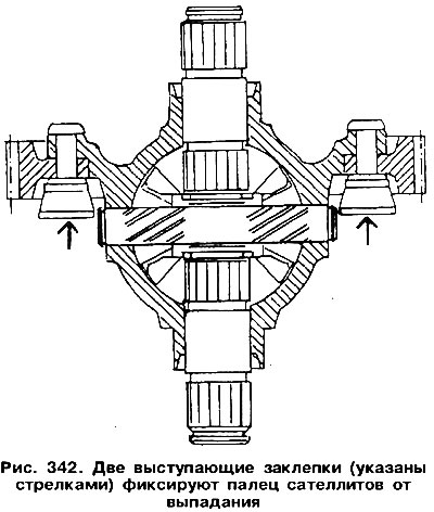
To disassemble the differential, it is necessary to cut off the heads of both rivets (see fig. 332) and knock out the pin of the satellites from the housing. When doing this, make sure that sawdust does not get into the bearings.
Remove the circlip from inside the crankcase.
Take out side gears and persistent plastic washers.
The differential housing bearings can be removed using a two-arm puller.
The disassembly of the input shaft can be done, guided by Fig. 343.
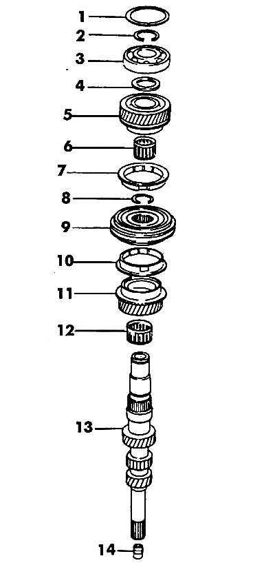
Pic. 343. Primary shaft: 1 - adjusting ring; 2 - retaining ring; 3 - ball bearing; 4 - spring washer; 5 - gear IV gear; 6 - needle bearing; 7 - blocking ring synchronizer IV gear; 8 - retaining ring; 9 - synchronizer III / IV gears; 10 - blocking ring of the synchronizer of III gears; II - gear wheel of the III gear; 12 - needle bearing; 13 - input shaft; 14 - sleeve
Remove the bearing 3. The release plate is inserted between the bearing and the V gear.
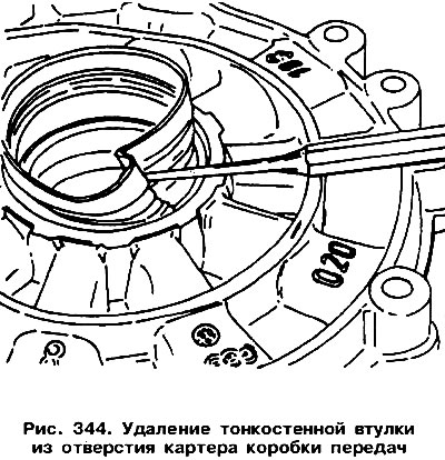
Remove the needle bearing 12. Description of the procedure for checking the condition of parts and gearbox assemblies presented here. It should be noted that in the case of replacing the gearbox housing, it is necessary to adjust the play when installing the main gear and input shaft. Replacing the shaft seal, clutch fork and gear selector rod is very simple. The worn seal must be removed with a screwdriver. A new oil seal, having lubricated the working edge, is installed in the socket with a piece of pipe of a suitable diameter. To replace the needle bearings of the secondary shaft, you need to use a special puller 771/15, as well as device 771. The axle drive shaft seal is replaced by knocking it out from the middle of the differential housing. A new stuffing box is installed in the socket from the outside and upset against the stop in the inner race of the bearing. In this case, the thin-walled bushing 9 should be removed (see fig. 341), crushing it with a punch to the middle, as shown in fig. 344. Carefully upset the new bushing without deforming it. In the same way, the outer race of the differential housing bearing is replaced. In this case, you must not lose the adjusting washer. After replacing the bearing, it is necessary to re-adjust the play in the meshing of the final drive gears.

Visitor comments