Before assembling the shaft, put the blocking ring of the synchronizer of III / LV gears on the cone of the corresponding gear and measure the distance between the gear and the ring (see fig. 295). The limit value due to wear is 0.5 mm.
If bushings and an oil seal installed in the crankcase wall are to be replaced, they must be knocked out from the inside with a 10 mm diameter rod. The new bushing is installed up to the stop. The seal has a gasket on the outside. After its working edge is lubricated, the stuffing box settles down until the lining is aligned with the surface of the crankcase, then the lining is removed.
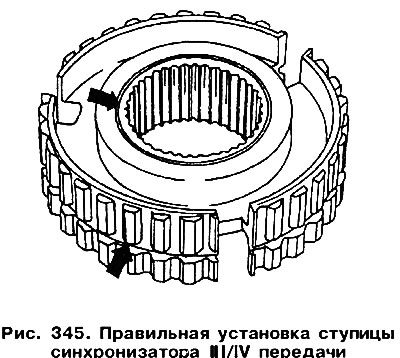
Insert three biscuits and a clip into the hub of the synchronizer of the III / LV gear. If new parts have been installed (hub and cage must always be replaced together), the hub must have a groove either on the flange (tops? arrow in fig. 345), or on the outer part of the hub (bottom arrow). The absence of a groove means that we have the wrong part in front of us. When installing the hub, its groove should be directed towards the gear of the 4th gear.

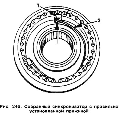
Insert the springs into the synchronizer body in the manner shown in fig. 346. The springs are on both sides of the synchronizer, their ends must be deployed 120°from each other.

Put the third gear with a needle bearing on the shaft (well oiled) and insert into the synchronizer housing, turning the ring so that the grooves and crackers are opposite each other.
To fix the synchronizer, take a new retaining ring, which must correctly fit into the groove on the shaft.
Fit the 4th gear with a needle bearing onto the shaft (well oiled) and force it into place.
Insert the ball bearing and shim into the gearbox housing. Pay attention to the fact that the closed side of the bearing is directed towards the 4th gear.

Visitor comments