- After dismantling the box, check the condition of the oil.
- Always replace all cardboard gaskets as well as seals. Before installing the oil seal, lubricate its working lip with clean oil.
- Thoroughly clean all surfaces mated with gaskets, if possible, lubricate them with sealant, paying attention to ensure that ventilation holes are not blocked.
- Always replace locking elements. Retaining rings must not be overstretched during installation.
- Always replace flare pins. When installing the pin, pay attention to the fact that the groove is located along the axis of the direction of action of the transmission.
- Bolts and nuts securing the rear crankcase cover loosen and tighten diagonally. Replace self-locking bolts and nuts. Pay attention to tightening torques.
- Install the needle bearing with the marking facing out.
- Lubricate all bearings generously before installation.
- Heat the inner races of tapered bearings to a temperature of 100°C before installation. Tapered bearings replace entirely (do not take clips from other bearings).
- The thickness of the shims is measured with a micrometer in several places. Only washers can be installed without any damage.
- Check up a condition of blocking rings of synchronizers and, in case of need, replace them. The condition of the synchronizers affects the correct operation of the gearbox. Before installing the synchronizer ring, it must be well lubricated so that there is no dry contact when first turned on.

Pic. 312. Components of the fifth gear under the cover: 1 - bolt (8 Nm); 2 - back cover; 3 - washer; 4 - clip; 5 - fork V transmission; 6 - latch; 7 - synchronizer hub; 8 - synchronizer ring; 9 - gear V gear; 10 - needle bearing; 11 - bushing; 12 - spring washer
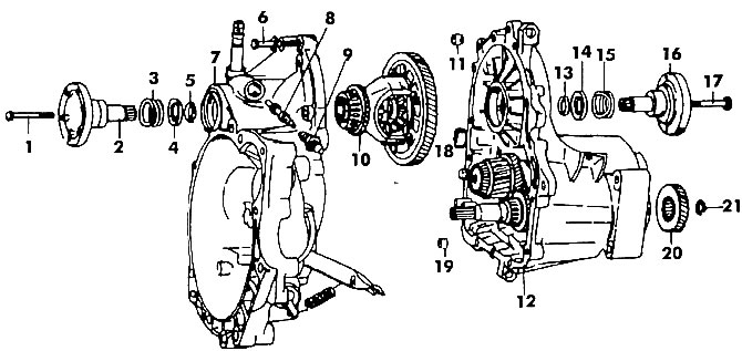
Pic. 313. Units and parts to be dismantled from both parts of the gearbox housing: 1 - bolt (25 Nm); 2 - right shaft with half shaft water; 3 - spring; 4 - spring washer; 5 - conical ring; 6 - bolt (25 Nm); 7 - part of the gearbox housing from the clutch side; 8 - speedometer drive; 9 - guide sleeve; 10 - differential; 11 - pin; 12 - the second part of the gearbox housing; 13 - conical ring; 14 - lock washer; 15 - latch; 16 - left axle drive shaft (with groove); 17 - bolt (25 Nm); 18 - magnet; 19 - locating pin; 20 - transmission gear; 21 - retaining ring
The design features of the gearbox are shown in fig. 312 and 313. To disconnect the crankcase, perform the following operations:
- Drain the gearbox oil. Insert a rod into one of the holes in the drive shaft flange and use a spanner wrench to unscrew the long bolt located inside the flange. The rod resting against the rib of the crankcase wall will not allow the shaft to turn.
- Using two pry bars under the flange, remove the drive shaft from the housing (see fig. 280). Please note that both shafts have different lengths and designations. The left shaft is shorter and has a milled groove behind the flange. Shafts cannot be interchanged.
- Remove the retainer on both sides 15 (see fig. 313), lock washers 14 and taper ring 13. The taper ring is directed towards the spring washer.
- Loosen three bolts (see fig. 312) rear cover 2 V transmission and take out the washer 3.
- Loosen the lock nut and remove the ball head bolt (arrow in fig. 314), pull down the forks 5 (see fig. 312) gears and clip 4.
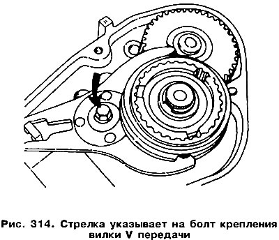
- Remove retainer 6. During installation, it can be replaced with an appropriately sized retaining ring.
- Place a two-arm puller under the 9 V transmission gear and remove the gear together with the synchronizer hub 7.
- Remove the needle bearing 10. Place a screwdriver under the spring washer 12 of the V gear and remove it together with the needle bearing bush 11. Remove retaining ring 21 (see fig. 313) and remove the 20 V transmission gear from the shaft using two screwdrivers. Remember how the gear was installed - its chamfer should be directed towards the tapered bearing.
- Loosen the bolts holding both parts of the gearbox housing together.
- Remove part of the crankcase (clutch side). Two pins are placed in the joint surface. A rubber mallet is required to separate the parts of the crankcase. In case of difficulty with separation, the pins should be knocked out of the housing.
Take out the differential. Turn out the directing plug of a drive of a speedometer. The details of the gearbox housing from the clutch side are shown in fig. 315. Replacing the stuffing box 16 of the drive shaft is a simple operation. The old seal is removed with a screwdriver. When replacing the stuffing box, its clip 15 should also be replaced. The old clip is also removed with a screwdriver, and the new one is pressed in with a mandrel of a suitable diameter. When installing a new oil seal, use a piece of pipe of a suitable diameter. Working edges need to be lubricated.
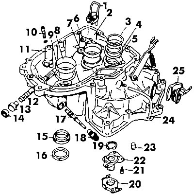
Pic. 315. Part of the gearbox housing from the clutch side: 1 - latch of the internal gear selection lever; 2 - clutch housing; 3 - tapered bearing race; 4. 5, 7 - shims; 6 - bearing race; 8 - tapered bearing race; 9 - washer; 10 - bolt (25 Nm); 11 - clutch; 12 - gear selection rod; 13 - lever bushing; 14 - stuffing box; 15 - stuffing box holder; 16 - stuffing box drive axle shaft; 17 - speedometer drive gear; 18 - bushing; 19 - input shaft seal; 20 - release bearing; 21 - bolt (18 Nm); 122 - guide sleeve; 23 - starter shaft bushing; 24 - breather tube; 25 - screw plug
The gland 14 of the gear selection rod is knocked out with a rod of a suitable diameter. The new oil seal is pressed flush with the crankcase. To remove the stem 12, knock out the sleeve 13 and remove the stem.
Bushing 23 of the starter shaft can be removed with a puller (VW 2046 and VW 2286). Press the new bushing flush with the inner surface of the crankcase. The outer race of the input shaft bearing is removed with a Kukko puller 1 (rice 316). Remove the adjusting washer 4 from under the bearing race (see fig 315). Washer 5 is not installed at the factory. A new bearing race is installed using a pipe of a suitable diameter, then the play of the input shaft is adjusted. These operations are also required in case of replacement of one of the parts of the gearbox housing, as well as the input shaft.
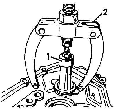
Pic. 316. Removing the outer qboyma tapered primary bearing (secondary) shafts: 1 - Kukko 21/5 puller (for input shaft); 2 - puller Kikko 22/2 (for output shaft)
Removing the tapered bearing race from the output shaft requires the use of a puller 2 (see fig. 316) . Remove the shim from under the bearing race. A new bearing race is installed using a pipe of a suitable diameter, but the backlash of the secondary shaft must first be adjusted. This adjustment is also necessary after replacing one of the parts of the gearbox housing, the output shaft or its bearing. To replace the input shaft seal 19 (see fig 315) it is necessary to remove the clutch release bearing 20 and the guide sleeve 22. Then remove the oil seal. Install a new oil seal so that the distance to the inner surface of the crankcase is 2.5 mm. Refit the bearing guide bushing by tightening the fixing bolts to 18 Nm.
If the clutch 11 was removed, then after unscrewing the bolt 10 and removing the gear selection rod, it should be adjusted during the installation of the clutch. Adjustment is also carried out when replacing components installed on one of the parts of the gearbox housing: the internal gear selection lever or a device that sets its position 1. A special tool will be required for adjustment. Do the following:
- On the gearbox housing, install a special plate 3154 with a bushing.
- Attach the stand VW 387 with indicator to the plate (rice 317, a).
- Attach the measuring rod of the indicator to the reverse gear engagement rod. Initially set the reading to 1 mm.
- Move the stem to the left and reset the indicator to zero. Move the stem to the right and read the indicator (e.g. 0.70 mm).
- Set the stem in the middle position, for this, divide the resulting value by two and move the stem from below by an amount (0.35 mm - for our example). In this position, secure the stem by tightening bolt 1 (rice 317, a).
- VW 709 special tool (rice 317, b) pull the selector in the direction of the reverse gear and attach the support 2. Move the support from stop to stop and read the indicator (e.g. 0.60 mm). Set the rod in the middle of the measured segment (0.30 mm for our example) and tighten bolt 3 (pic. 317, in) .
- Unscrew the indicator stand. Loosen bolt 4 (pic. 317, g) enough to allow the clutch to move freely on the selector shaft. Set the lever to the middle position.
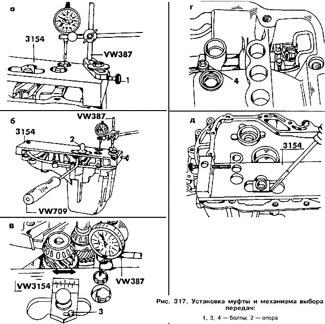
Install pins into the gearbox housing from the clutch side and install plate 3154 on its surface (pic. 317, d) and rotate 180°. Gear selector and clutch must be mounted on the same axle. If necessary, help yourself with a screwdriver, as shown in Fig. 317. The input shaft can only be removed in tandem with the output shaft. If the input shaft or tapered bearing has to be replaced, remember the input shaft installation sequence.
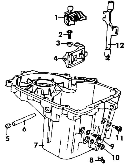
Pic. 318. Components installed in the gearbox housing: 1 - gear selection mechanism (during installation must be correctly oriented); 2 - bolt (16 Nm); 3 - bushing; 4 - clip; 5 - plug; 6 - gear connection rod; 7 - gearbox housing; 8 - lock V transmission; 9, 10, 11 - threaded plug; 12 - rocker V gear
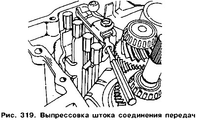
Separate both parts of the gearbox housing (see here). After removing plug 5 (pic. 318) knock out stem 6 using a thin rod, which is applied as shown in fig. 319. If the gear selection mechanism 1 has to be removed, it should be remembered that it is mandatory to adjust its installation during assembly so that it is on the same axis as the clutch. Clip 4 can be removed after unscrewing bolt 2 and removing sleeve 3.
Unscrew two screw plugs 9 and 10 from the side of the crankcase and take out the parts under them.
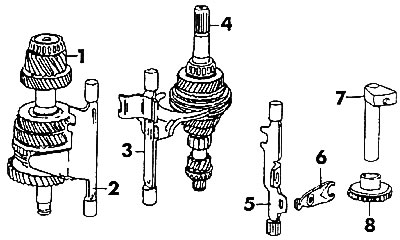
Pic. 320. Set of gears: 1 - secondary shaft; 2 - stock I / II gears; 3 - rod with forks III / IV gears; 4 - input shaft; 5 - reverse rod; 6 - reverse gear engagement lever; 7 - reverse gear shaft; 8 - reverse gear
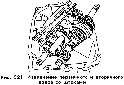
From the crankcase, remove the bolt that secures the reverse gear shaft. Knock out shaft 7 (pic. 320) reverse gears. Remove from crankcase at the same time (pic. 321) primary and secondary shafts, reverse gear with shaft, as well as both rods.
Disassemble the extracted nodes into separate parts (see fig. 320).

Visitor comments