Install the reverse gear shaft.
Screw two M8 studs into the bearing cage, which will serve as guides for the crankcase.
Attach special bracket (see fig. 338) and connect both parts of the crankcase, helping yourself with a rubber mallet. Don't forget to install a shim under the bearing. Install the reverse shaft bolts. Screw in the reversing light switch or the gear selection and fuel consumption indicator.
Fasten the ball bearing mounting plate with bolts, tightening them with a torque of 15 Nm.
Tighten the crankcase halves bolts to 25 Nm.
Among these bolts there are two shorter bolts, they are installed below the clutch housing bolts.
The installation of the drive shafts is shown in rice. 350.
Install a retaining ring on the shaft and move it with a fitting of a suitable diameter until it fits into the annular groove.
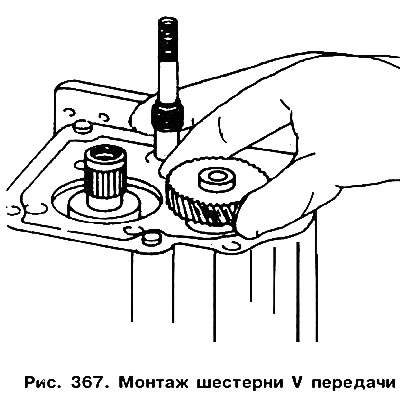
Heat the V gear to 100°C and put it on the shaft, pointing the groove up (pic. 367). Install the spring washer and circlip.

Put the synchronizer hub together with the gear under the forks and insert a new locking plate.
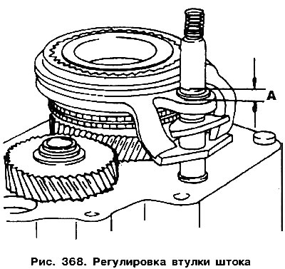
Screw the stem bushing onto the fork (see fig. 361), and then turn it out slightly so that it protrudes 5.0 mm (size «A» in fig. 368).

Attention! When removing the spanner wrench, the stem must not be pulled out, as the components of the gear selection mechanism will disengage and the gearbox will have to be disassembled again.
Set the forks in position «gap» and insert the shift shaft. To do this, you need to install the box crankcase horizontally, fix the sheet material cover with a piece of wire so that it cannot turn (see fig. 363).
Install spring and cover.
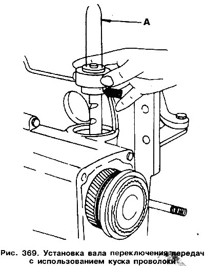
Insert the bolts fixing the V gear, as well as the gear shift shaft (pic. 369) using a piece of wire. The ends of the wire should protrude from below (see arrow).

Install the bolts and the gearshift shaft as described here.
Place the control lever on the shift shaft and engage V gear by pulling out the shift shaft and turning it to the left.
Slightly lift the synchronizer cage together with the forks to eliminate gaps in the parts.
Cover the new synchronizer hub bolt with a fixing compound «D6», then with a 12 mm rod wrench («Polygon») tighten with a torque of 150 Nm (see fig. 359). To lock the rod, engage reverse gear or V gear.
Check the correct engagement of the coupling sleeve with the pinion. The degree of overlap should be 1 mm. Otherwise, you need to change the position of the stem sleeve (see fig. 361).
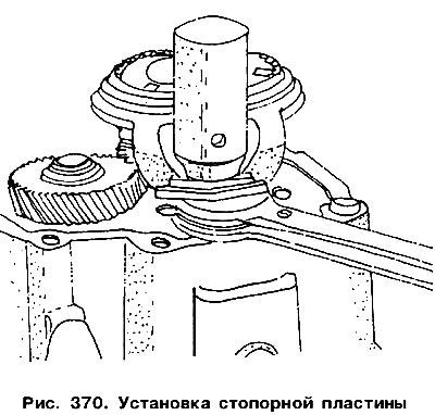
Install the stop plate using tool Nq 3097. The tool must be installed as shown in fig. 370. Place two flat keys 19 and 24 mm under the plugs.

All other operations are performed in the reverse order of disassembly.

Visitor comments