Removing
1. Golf cars. Remove the fairing grille, see the relevant chapter.
2. Golf Plus/Touran cars. Remove the glass cleaner motor, see relevant chapter.
Attention! The performance of these works is necessary to provide access to the upper supports of the shock absorber struts on the mudguards.
3. Unscrew the hub bolt.
Attention! When loosening the hub bolt, the car must be on its wheels, because the tightening torque of the nut is large enough and an accident may occur if it is unscrewed while the car is jacked up.
Attention! Unscrewing a loose hub bolt should be done with the car jacked up to relieve the suspension.
4. Mark the position and direction of the wheel to be removed on the hub with paint. This will allow the assembly to set the balanced wheel in its original position.
5. Unscrew the bolts of the wheel to be removed and remove it.
6. Unscrew the top nut of the anti-roll bar link on the suspension strut (see arrow in illustration). At the same time, keep the rack mounting bolt from turning with an M6 multi-faceted socket wrench.
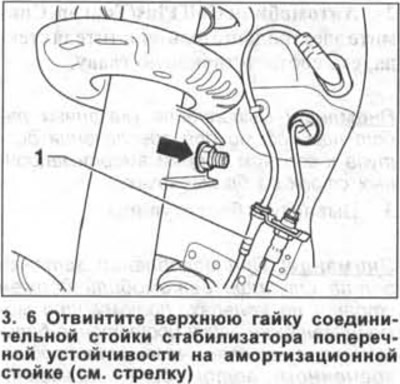
7. Remove the rack mounting bolt and disconnect it.
8. Release the wire 1 of the ABS sensor from the mounting on the suspension strut (see illustration 3.6).
9. Mark with a scriber the mounting position of the three mounting nuts on the transverse arm and unscrew them.
10. Disconnect the ball joint from the transverse arm.
11. Remove the outer CV joint from the hub with your hands. Do not pull on the drive shaft.
Attention! Press the tightly fitting driveshaft shank out of the hub using a puller such as HAZET 2515-1.
12. Fasten the drive shaft with wire to the body to prevent maximum bending of the CV joints when dismantling the shaft.
13. Attach the ball joint to the transverse arm.
14. Support the steering knuckle with a suitable jack.
Attention! Do not install a jack under the ball joint.
15. Unscrew a nut of a carving connection of an amortization rack with a rotary fist and take a bolt of fastening (see arrow in illustration).
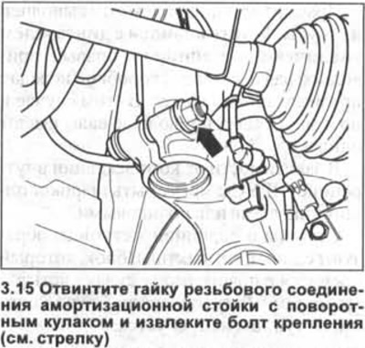
Attention! The bolt and nut are not reinstalled. They must be replaced with new ones.
16. Insert a suitable expanding shaft 1, e.g. VW 3424, into the slot on the steering knuckle and turn it 90°using a socket (see illustration). Leave the roller in the slot, and remove the head. If necessary, make your own expanding roller with dimensions: a = 8 mm, b = 5.5 mm. Round the edges of the roller.
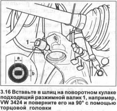
17. Press the brake disc against the shock strut, because the shock absorber tube may get stuck in the hole on the steering knuckle.
18. Slowly lower the support jack and remove the steering knuckle from the suspension strut.
19. Secure the steering knuckle to the subframe with wire and remove the support jack.
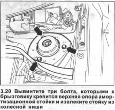
20. Unscrew the three bolts that secure the upper suspension strut support to the mudguard and remove the strut from the wheel arch by lowering it down (see arrows in illustration).
Installation
21. Insert the suspension strut into the wheel arch and secure its upper support to the mudguard. At the same time, make sure that one of the marks in the form of an arrow on the upper support cup of the spring is facing the direction of the vehicle.
22. Install the upper suspension strut mount with new self-locking bolts, tightening in two passes.
- The 1st pass is made with a torque wrench with a tightening torque of 15 Nm.
- The 2nd pass is made with a regular wrench and the bolt is turned 90°.
Attention! In order for the angle of rotation to be exactly maintained, it is recommended to cut out a goniometer from cardboard or use the HAZET 6690 template.
23. Support the steering knuckle with a jack and insert the spring strut tube into the hole on the steering knuckle.
24. Disconnect the steering knuckle attached to the subframe and carefully lift it with a jack to align the holes and insert a new shock absorber mounting bolt on the steering knuckle.
Attention! Insert the bolt into the hole so that its end is facing in the direction of the car.
Attention! Do not install a steering knuckle jack under the ball joint.
25. Squeeze the brake disc to the shock absorber when lifting the steering knuckle. Make sure that the spring strut tube is not warped in the steering knuckle hole.
Attention! To avoid damage to the silent block, tighten the lower threaded connection only after the vehicle suspension is under load. Before doing this, on an unladen vehicle, measure the distance -a- (see illustration).
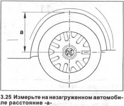
26. Raise the wheel hub so that the pressure on it corresponds to the load that it experiences when the car is standing on the wheels, unladen. This means that the steering knuckle must be raised with a jack so that the distance between the center line drawn in the center of the hub and the lower edge of the wheel arch is within the value -a-, which for Golf cars is 356 m (see illustration 3.25).
27. Screw on a bolt of fastening of an amortization rack to a rotary fist a new nut and take the spacer roller from a slot of a rotary fist.
28. Tighten the threaded connection of the spring strut on the steering knuckle in two passes.
- The 1st pass is made with a torque wrench with a tightening torque of 70 Nm.
- The 2nd pass is made with a regular wrench and the bolt is turned 90°.
Attention! In order for the angle of rotation to be exactly maintained, it is recommended to cut out a goniometer from cardboard or use the HAZET 6690 template.
29. Remove the jack from under the steering knuckle.
30. Unscrew three nuts of the spherical hinge and disconnect the hinge from the cross-section lever.
31. Insert the drive shaft shank into the hub. Make sure that the CV joint boot is not damaged or twisted.
32. Attach the ball joint to the transverse arm.
Do not damage or twist the protective cap of the ball joint.
33. Screw a new self-locking nut onto the ball joint pin and tighten it to 75 Nm.
34. Fix in the holder on an amortization rack a wire of gauge ABS.
35. Fix a new nut rack of the anti-roll bar on an amortization rack.
The tightening torque of the nut is 65 Nm. When tightening the nut, hold the mounting bolt from turning with a multi-faced socket wrench M6.
36. Screw in a bolt of fastening of a nave, the corresponding chapter see.
Attention! When the bolt is first tightened, the vehicle must not be on wheels.
37. Establish a forward wheel according to the marks put at removal.
38. Screw in the wheel bolts and lower the car onto the wheels.
39. Tighten the bolts, acting in a crosswise manner, with a torque of 120 Nm.
40. Golf cars. Install the fairing grille, see relevant chapter.
41. Cars Golf Plus/Touran. Reinstall the windshield wiper motor.

Visitor comments