Warping of the mating plane of the head with the cylinder block, not more than, mm: 0.1.
Permissible height of the cylinder head after grinding, not less than, mm: 132.60.
Valve seats
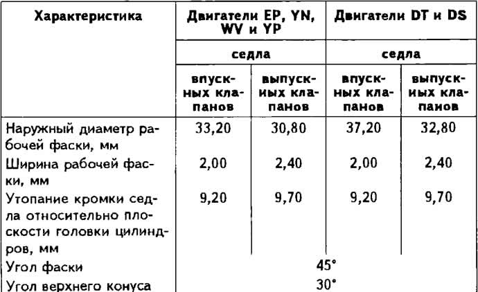
The valve seats are made from powder metallurgy steel and are non-replaceable. If signs of burning or wear are found that cannot be removed by grinding, replace the cylinder head.
Valve seat specifications

Valve guides
The valve guides are made of special brass and are pressed into the cylinder head.
Maximum allowable limit clearance (when worn) between valve stem and guide sleeve, mm:
- for inlet valves: 1.0;
- for exhaust valves: 1.3.
Hole diameter in valve guide bushings, mm: 8.013-8.035.
Valves
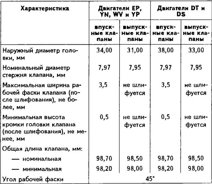
The valves are located in the cylinder head in a row at an angle of 90°to the vertical axis of the cylinders and are actuated directly by the camshaft cams through the pushers. Exhaust valves are not subject to grinding.
Valve characteristics

Clearances in the valve drive mechanism
The gap between the camshaft cams and shims at a coolant temperature above 35°C should be 0.25±0.05 mm for intake valves and 0.45±0.05 for exhaust valves, on a cold engine, respectively 0.20±0.05 and 0.40±0.05 mm.
The gap is adjusted by selecting the thickness of the shims mounted on the upper ends of the pushers. Spare parts are supplied with shims with a thickness of 3.00 to 4.25 mm at intervals of every 0.05 mm.
Note. From May 4981, in the upper part of the valve stems, there were three annular grooves for the protrusions of crackers instead of one. When replacing crackers and weapon plates, install valves of a modified design. On the same engine, it is permissible to install valves of both the previous and modified designs.
Valve springs
Each intake and exhaust valve has two springs. The intake and exhaust valve springs are the same.
Pushers
The valve lifters are located directly in the cylinder head. Adjusting washers of various thicknesses are installed on the upper ends of the pushers to adjust the thermal clearances of the valves.

Visitor comments