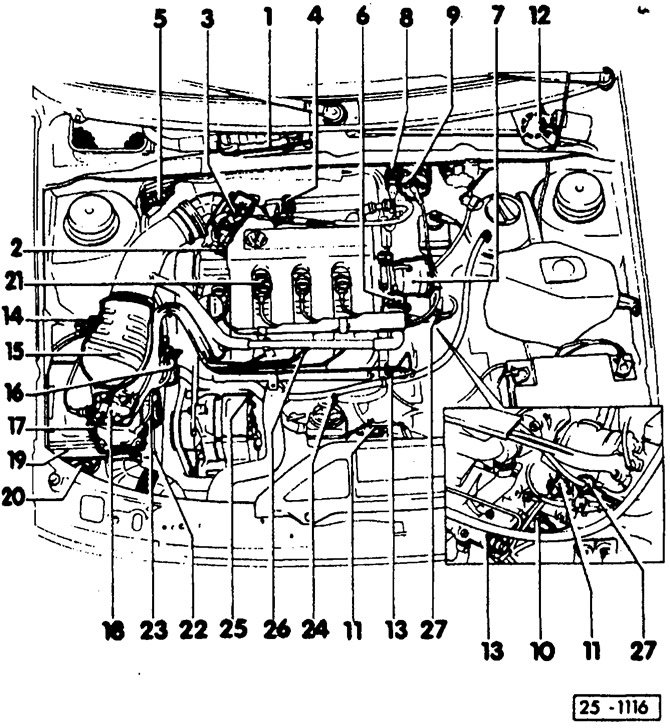
- 1 - control unit of the KE-Motronic system
- 2 - throttle angle sensor
- 3 - throttle valve
- 4 - CO sampling tube
- 5 - plug connector For oxygen sensor.
- 6 - the control valve of the system for stabilizing the engine shaft speed at idle
- 7 - ignition distributor
- 8 - voltage output stage
- 9 - ignition coil
- 10 - temperature sensor of the KE-Motronic system
- 11 - plug connectors
For knock sensors.
- 12 - fuel pump relay
Under the instrument panel, in turnip position 12.
- 13 - starting fuel valve
- 14 - solenoid valve
For activated carbon system.
- 15 - air flow meter
- 16 - membrane pressure regulator
- 17 - potentiometer
- 18 - fuel dispenser
- 19 - air filter
- 20 - container with activated carbon
- 21 - spark plug
- 22 - control damper
For intake air heating system.
- 23 - pressure regulator
- 24, 25 - knock sensors
- 26 - valve nozzle
- 27 - sensor of the ignition timing control system
On the high voltage wire for cylinder 4.
The KE-Motronic system is a combined ignition and injection system controlled by a common electronic control unit. The injection part is structurally similar to the K-Jetronic system, but has an additional electronic control. Thanks to electronics and additional sensors, more parameters can be involved and processed to control the amount of fuel injected. In addition, adjustment of the oxygen sensor for catalyst operation is facilitated. The engine idle warm-up regulator and the pressure regulator in the system are not needed with KE-Motronic.
The electro-hydraulic actuator located at the fuel dispenser regulates the amount of fuel supplied to the valve injectors depending on the engine load mode. This means that the final link provides enrichment of the mixture during cold start-up and warm-up, as well as during acceleration and full engine load. In addition to this, the executive link shuts off the fuel supply when the engine is running in forced idle mode.
The membrane pressure regulator at the fuel dispenser maintains the pressure in the system in the range of 6.1-6.6 bar.
The activated carbon system prevents harmful fuel vapors from entering the atmosphere, the released vapors accumulate in the activated carbon tank. During vehicle operation, the vapors, the flow of which is controlled by two solenoid valves, are sent to the engine for combustion. The memory device in the control unit during operation recognizes the malfunctions that occur and accumulates the codes of these malfunctions. If important sensors fail, the control unit switches to a temporary program in order to avoid stopping the engine. In the VAG workshop, fault codes are determined and purposefully eliminated.
Attention: When working on mechanical injection systems, attention must be paid to impeccable cleanliness. Before dismantling, the relevant parts must be cleaned with petrol. The system is under high pressure. Therefore, before replacing pressure reducing parts, slowly unscrew the fuel line at the fuel start valve. Put a rag under the fuel line first. Caution: risk of splashing! Collect spilled fuel with a rag.

Visitor comments