The hydraulic brake drive includes the main brake cylinder and the hydraulic brake booster. The hydraulic drive of the front brakes is separate for the right and left wheels, it is controlled by the main brake cylinder. The hydraulic drive of the brakes of the rear wheels with a Y-shaped connection is controlled by an amplifier. The brake discs of the front wheels are ventilated, and the rear wheels are solid.
On car parts ««Passat» production since July 1995, an anti-lock brake system ITT Automotive Europe, Teves 20 Gi and an ABS / EDS Teves 20 Gi system, which is a combination of an ABS system and a differential lock system, have been installed.
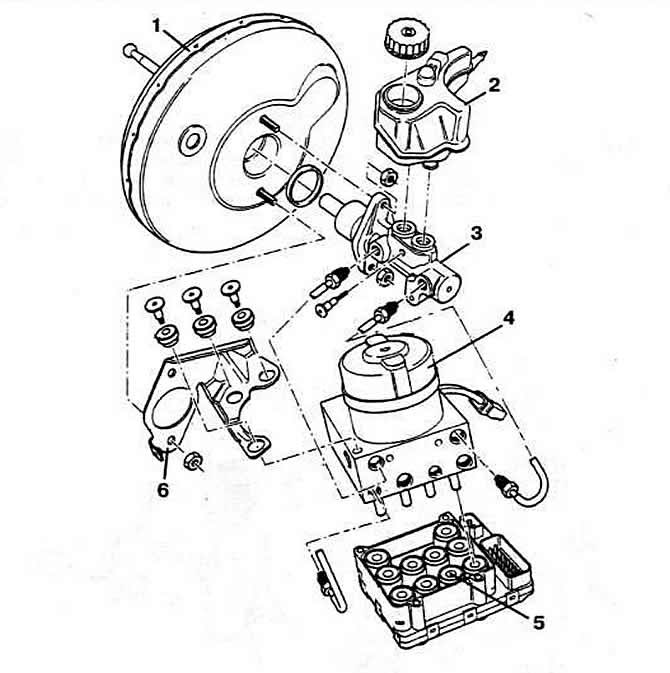
The ABS braking system consists of two independent circuits divided diagonally. A vacuum booster is included in the brake drive. The brake drive of vehicles with ABS and the Teves 20 Gi ABS / EDS system does not have a mechanical pressure regulator, since the pressure in the wheel cylinders of the rear wheel brake mechanisms is regulated by the ABS electronic control unit according to a specially developed program. Hydraulic unit and ABS electronic control unit (pic. 7-5) merged into one node. Their separation is possible only after removing this node.

Pic. 7-5. Details of the valve body assembly with the electronic ABS brake control unit ITT ATE 20 GI:
1 - vacuum brake booster;
2 - tank;
3 — the main brake cylinder with two coaxial pistons;
4 - ABS valve body;
5 - electronic control unit;
6 - bracket.
Device Features
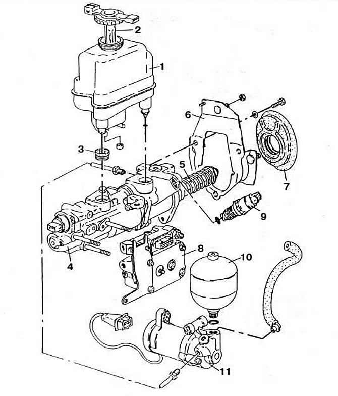
The anti-lock braking system consists mainly of wheel pulse generators (rotation speed sensors), hydraulic unit (pic. 7-6) and electronic control unit.

Pic. 7-6. ABS valve body parts:
1 - reservoir of the hydraulic unit;
2 - tank cap;
3 - sealing gasket;
4 — knot of the booster of brakes and the main brake cylinder;
5 - pusher;
6 - mounting bracket;
7 - rubber seal;
8 - valve box;
9 - overpressure sensor;
10 - pressure accumulator;
11 - high pressure pump.
Pulse generators installed on each wheel provide wheel speed signals to the electronic control unit.
An electronic control unit installed under the rear seat provides control signals for the hydroblock solenoid valves, depending on the signals. received from each wheel sensor. In addition, it has a self-control circuit. which, by turning on the warning lamp on the instrument panel, warns the driver of a system malfunction.
Hydraulic unit installed in place of the conventional brake master cylinder. includes a master cylinder with two coaxial pistons that supplies brake pressure to the front wheels, a hydraulic brake booster that supplies brake pressure to the rear wheels, and six pressure control solenoid valves. three of which are connected to the hydraulic brakes, and the rest - to the discharge circuit.
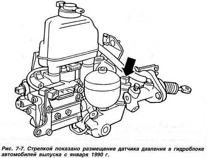
Note. Since January 1990, the pressure sensor is not installed at the end of the master brake cylinder, but on the ABS high pressure pump (pic. 7-7), which is supplied in spare parts only with a hole for installing the sensor. on the master cylinders. supplied as spare parts. the hole for the sensor is closed with a plug. In the case of installing a pump of a modified design with a master cylinder of the previous design, install a pressure sensor on the pump and plug the hole in the brake master cylinder.

System check
The ABS system of the 1990 model year is equipped with a self-diagnosis system, which is the same in principle as the self-diagnosis system of the central fuel injection system «Mono-Jetronic» and KSUD «KE-Motronic» (see relevant subsection).
Interrogation of the memory device of the self-diagnosis system can only be carried out using the VAG 1551 reader.
Checking the electrical circuits of the ABS is carried out through the terminals of the connector of the electronic control unit. The check is carried out in the following cases:
- on cars manufactured before January 1990 not equipped with an ABS self-diagnosis system;
- if, when reading fault codes, it is not possible to establish the location of the fault;
- if a more accurate check is required when determining any DTC.

Visitor comments