Device Features
Cylinder head cast aluminum alloy (pic. 2-14). The valve seats and valve guides are pressed into the cylinder head. The camshaft bearings are made directly in the body of the cylinder head. Tolerance of flatness of pairing of the head with the cylinder block, not more than, mm: 0.1.
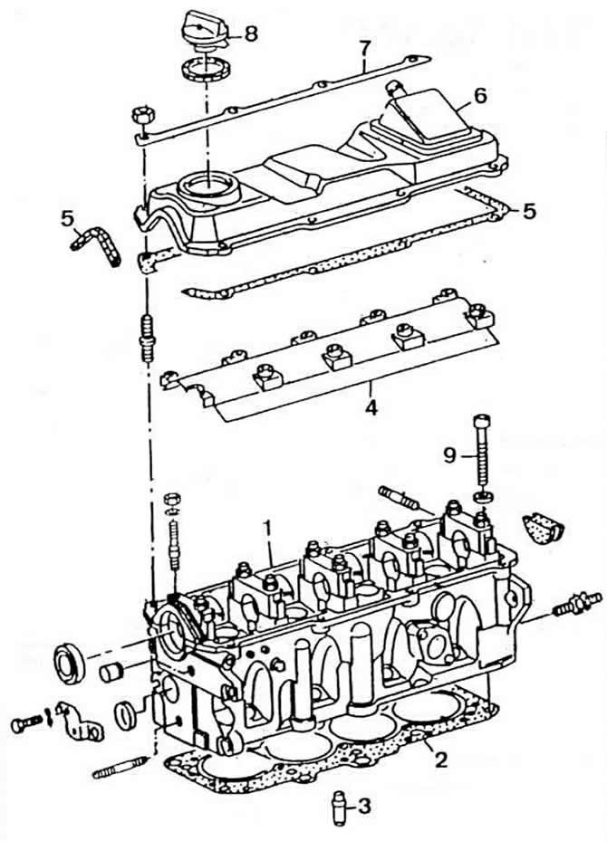
Pic. 2-14. Cylinder Head Details:
1 - cylinder head;
2 - cylinder head gasket;
3 - valve guide sleeve;
4 - oil deflector;
5 — laying of a cover of a head of cylinders;
6 - cylinder head cover;
7 - stiffness bar;
8 - oil filler plug;
9 - cylinder head bolt.
The cylinder head gasket is installed with a label «Oben» («Top») up.
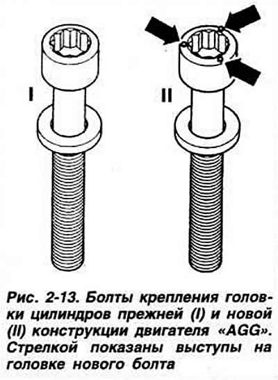
Since March 1995, a new metal cylinder head gasket has been installed on the AGG engine, which required the use of special cylinder head bolts. When repairing the engine, it is allowed to install a new cylinder head gasket on engines of previous releases, provided that the indicated new cylinder head bolts are used.
The bolts used with the old cylinder head gasket have a smooth head end, and the head end of the new bolts has three lugs (pic. 2-13). The order and tightening torque of the bolts remained unchanged.
Valves are made of special steel. located in the cylinder head in one row above the cylinders vertically and are driven directly by the camshaft cams through hydraulic tappets. The valve stems have oil seals.
Valves are not subject to grinding. It is only allowed to grind them. The sinking of the ends of the valve stems is measured between the mating surface of the cylinder head and the end of the stem, as indicated in subsection «Dismantling, checking the technical condition and repair of the cylinder head».
The valve seats are made of powder metallurgy steel. Valve seats may only be replaced at a workshop. When traces of burning or wear are found that cannot be removed by grinding while maintaining the angles of the working chamfer, the upper cone and the width of the chamfer. in operation, the cylinder head as a whole is replaced.
Note. Grinding of valve seats is done only to obtain the desired surface quality. Before grinding, determine the maximum allowable grinding size (distance from the end of the valve stem to the mating surface of the cylinder head). With a decrease in the specified size, automatic adjustment of the clearances in the valve drive mechanism by hydraulic tappets is not provided. In this case, the cylinder head must be replaced.
The valve guides are made of brass and are pressed into the cylinder head.
The maximum allowable indicator reading for wear in service between the valve stem and guide sleeve for inlet valves is 1.0 mm. for exhaust valves 1.3 mm. The diameter of the hole in the valve guides is 8.013-8.035 mm.
Each intake and exhaust valve has two springs. The intake and exhaust valve springs are the same.
Hydraulic pushers
Design.The hydraulic pusher consists of two main moving parts: the pusher itself 2 (pic. 2-15), which simultaneously serves as a plunger during operation, and cylinder 4.
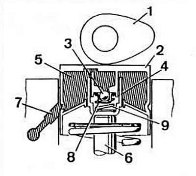
Under the pressure of the spring 9, the plunger and the cylinder move away from each other, due to which the gap between the camshaft cam and the end of the valve stem is selected.
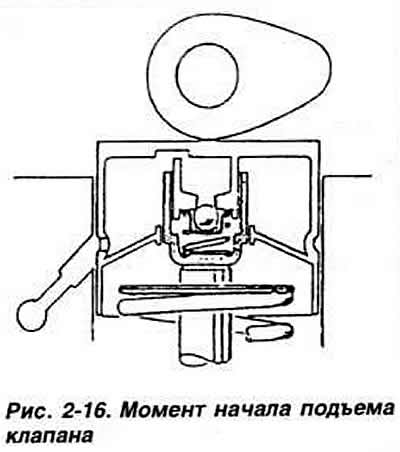
High-pressure chamber 8 is locked by check valve 3. Operating principle. At the start of valve lift (pic. 2-16). those. at the moment the camshaft cam hits the end of the pusher, the check valve closes the chamber and the pressure in it increases. An increase in pressure does not compress the volume occupied by the oil in the pressure chamber. The pusher thus works as a rigid body.
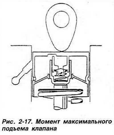
At the moment of maximum valve lift (pic. 2-17) the camshaft cam presses the pusher with force, which leads to a significant increase in pressure in the pusher cavity. A small amount of oil is ejected through leaks between the cylinder and the plunger, which causes the hydraulic tappet to be compressed by a maximum of 0.10 mm. Such compression is structurally necessary for running-in pushers with a decrease in the distance between the camshaft cam and the end of the pusher. Gap compensation between cam and pusher (pic. 2-18) happens as follows. The camshaft cam does not press on the tappet, and the pressure in the high pressure chamber drops. The spring separates the plunger and the cylinder, thereby choosing the gap between the cam and the end of the valve stem.
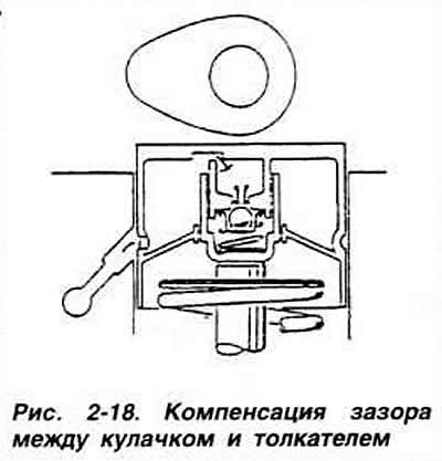
At this point, the check valve opens. some oil enters the high pressure chamber. This amount depends on the size of the selected gap.
Note. Increased noise of the valve train actuator after starting the engine is normal. It's related to that. that when the engine is stopped, part of the oil flows out of the cavity of the pushers. When the engine starts, the high pressure chamber refills and the noise stops. The filling of the high pressure chamber continues until the engine has warmed up to operating temperature. The design of the lubrication circuit of the cylinder head prevents the complete removal of oil from the channels after the engine is stopped. This ensures that oil is supplied to the tappets immediately after the engine is started and the noise in the valve train drive stops as soon as possible.
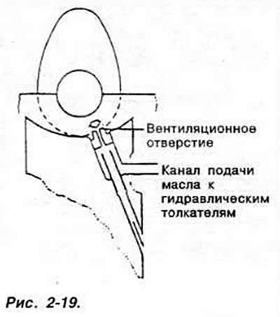
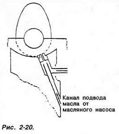
The operation of the hydraulic pushers at the time of starting the engine is shown in fig. 2-19 and 2-20. After the engine stops, oil drains from the channels coming from the oil pump. and the channels for supplying oil to the pushers remain filled with oil. In order to prevent air from entering under the action of oil pressure into the cavity of the pusher at the time of starting the engine, there are ventilation holes in the channels for supplying oil to the pushers, which provide automatic purging of the pusher cavity. In addition, the vent hole allows you to reduce the pressure of the oil entering the pushers.
Hydraulic tappets are installed directly in the cylinder head. The valves are driven by camshaft cams through hydraulic tappet plungers. The free travel of the pusher pistons is not more than 0.1 mm.
The gaps in the valve drive mechanism are compensated automatically by hydraulic tappets.
The camshaft is mounted in five bearings made directly in the body of the cylinder head. The diameter of the holes of the camshaft bearings is 26.00-26.02 mm.
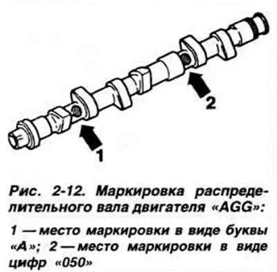
Engine camshafts have the following markings in the form of letters and numbers stamped between the intake and exhaust cams of the first and third cylinders:
- «EZ»: «M-026».
- «RP»: «N» or «0-026»;
- «RV»: «G-026»;
- «2E»: «A-026»;
- «AGG»: «A-050» (pic. 2-12).
Note. Spare parts can be supplied with cylinder heads or engines with camshaft bearing shells. Camshafts of reduced repair dimensions are not supplied as spare parts. When repairing, install a camshaft with nominal dimensions with the appropriate bushings. Such camshafts have a yellow mark according to VW Audi standards.
The drive of the intermediate shaft is carried out by a toothed belt of the camshaft drive. The intermediate shaft drives the oil pump, the ignition distributor, and on the engine «EZ» and fuel pump.
Axial clearance of the intermediate shaft is not more than 0.25 mm
Toothed belt brand and type Pirelli 121 RX 180.
The tension of the belt is considered normal if, in the middle of a long branch, the belt is twisted no more than 90°by the force of the thumb and forefinger.

Visitor comments