The piston diameter is measured at a distance of 10 mm from the lower edge of the piston skirt at an angle of 90°relative to the axis of the piston pin.
Piston diameters are shown in Table 3-2.

Piston pins are hollow, steel, floating type. Piston pins are manufactured with high precision, carburized and hardened. As spare parts, piston pins are only supplied complete with pistons. Three rings are installed on each piston: two compression and one oil scraper. The joints of the compression rings and the components of the oil scraper ring are separated by 120°.
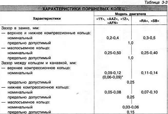
Rings are installed on the piston with a mark «Thor» («Top») to the bottom of the piston. Piston ring specifications are shown in Table 3-3.

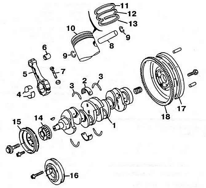
Connecting rods are steel, forged, with an I-section rod. A cap of the lower head of a connecting rod of direct section. The maximum permissible gap in operation between the liners and the connecting rod journals is 0.12 mm. The maximum axial clearance of the connecting rod on the crankshaft journal is 0.37 mm. Details of the crank mechanism are shown in fig. 3-8.

Pic. 3-8. Details of the crank mechanism:
1 - crankshaft;
2 - insert of the main bearing;
3 - persistent half ring;
4 - connecting rod bearing shell;
5 - connecting rod;
6 - bushing of the upper head of the connecting rod;
7 - connecting rod bolt;
8 - piston pin;
9 - retaining ring;
10 - piston;
11 - top compression ring;
12 - lower compression ring;
13 - oil scraper ring;
14 - toothed pulley of the crankshaft;
15 - crankshaft pulley;
16 - crankshaft pulley with torsional vibration damper;
17 - flywheel;
18 - ring gear.

Visitor comments