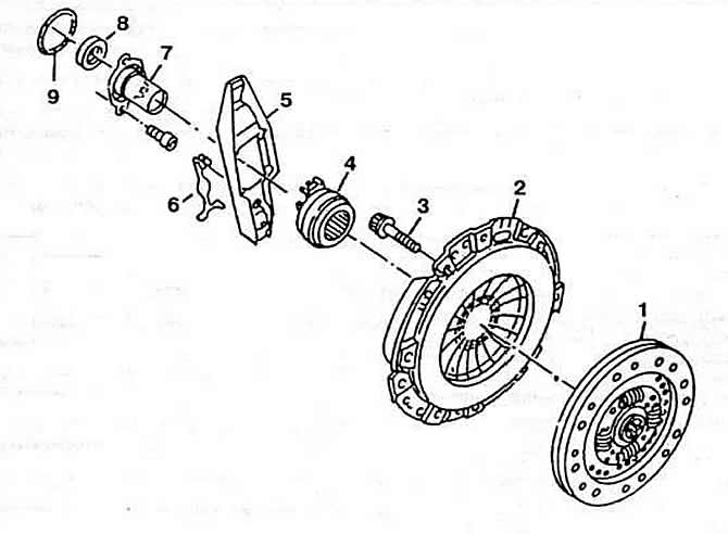
Pic. 4-1. Clutch details:
1 - driven disk;
2 - clutch cover assembly with pressure plate;
3 - fastening bolt;
4 - clutch release bearing;
5 - clutch release fork;
6 - retaining spring;
7 - bearing guide sleeve;
8 - sealing ring;
9 - gasket.
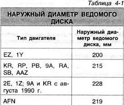
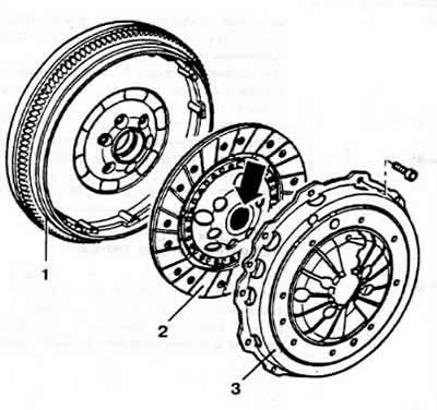
Driven clutch disc with elastic hub. The dimensions of the driven disk are shown in Table 4-1. Clutch release bearing ball, self-centering. On vehicles with AFN diesel, a dual-type flywheel with a torsional vibration damper, a new design clutch and an anti-vibration weight on the gear change drive are used (pic. 4-2). The flywheel consists of two parts, one of which is connected to the crankshaft flange. The other part is connected to the clutch cover and is the working surface of the clutch mechanism. Between the parts of the flywheel there is a torsional vibration damper of a spring type, in addition to which a friction torque limiter is used, which protects the engine from overloads during starting and stopping the engine, with a sharp engagement of the clutch, and also eliminates the vibration of the power unit.


Pic. 4-2. AFN Engine Clutch Details:
1 - flywheel;
2 - driven disk;
3 - clutch cover assembly with pressure plate.
The inner diameter of the clutch master cylinder is 15.80 mm. The gap between the piston and the cylinder is not more than 0.15 mm. The inner diameter of the working cylinder is 18.10 mm. The maximum allowable non-flatness of the flywheel surface under the driven disk in operation is 0.2 mm.
The maximum allowable end runout of the driven disk is 0.8 mm.
The hydraulic clutch release reservoir is common with the hydraulic brakes.

Visitor comments