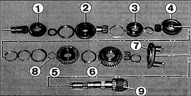
Pic. 4-29. Output shaft details
1 - gear IV gear;
2 - synchronizer III and IV gears;
3 — a gear wheel of the III transfer;
4 — a gear wheel of the II transfer;
5 - synchronizer of I and II gears;
6 - gear 1st gear;
7 - front bearing cover;
8 - retaining ring;
9 - secondary shaft.

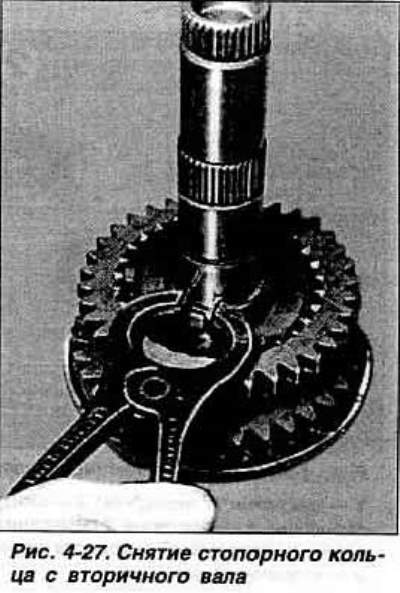
Remove retaining ring (pic. 4-27).

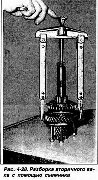
With the help of a universal two-jaw puller, wound up behind the 1st gear gear (a shoulder is made to install the puller grips in the front bearing cap) (pic. 4-28). remove the hub with the 1st and 2nd gear synchronizer clutch with the 2nd gear synchronizer blocking rings, the 1st gear synchronizer blocking ring, the 1st gear gear with a needle bearing, then the thrust washer.

Note. Starting with CP No. 3006 9 of June 30, 1989, the front bearing cover does not have a shoulder for the puller grips, and the grips are brought under the bearing. The new bearing cap is interchangeable with the old one.
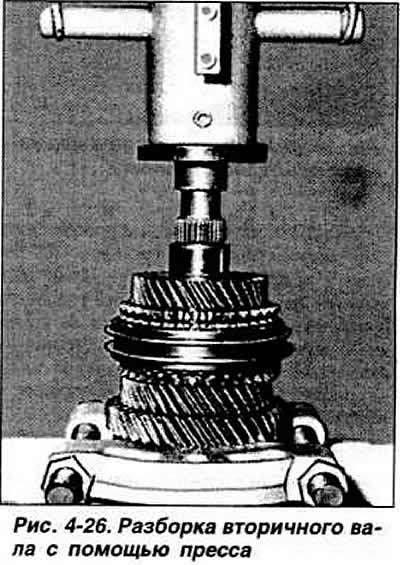
Using a base plate and a press, remove the tapered roller bearings. Using a press, remove the needle bearing from the gearbox housing. Press bearing inner race out of cover. Using an internal puller, press the bearing outer race out of the clutch housing and remove the adjusting ring.

Visitor comments