Drive shaft with ball joint

- 1 - retaining ring,
- 2 - gasket,
- 3 - inner CV joint,
- 4 - drive shaft,
- 5 - collar,
- 6 - protective cover,
- 7 - collar,
- 8 - washer,
- 9 - thrust ring,
- 10 - retaining ring,
- 11 - outer CV joint,
- 12 - bolt,
- 13 - bolt,
- 14 - plate,
- 15 - protective cover of the hinge with a flange
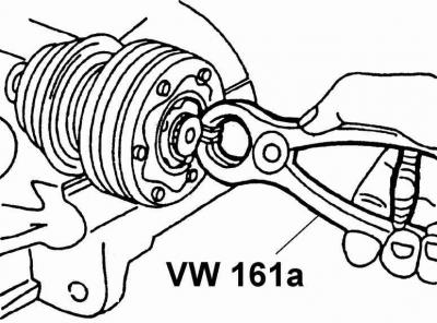
Warning: Removal of retaining ring 1 is carried out using round nose pliers.
Warning: When installing a new gasket 2, a new gasket must be used. Remove the protective film from the gasket and stick the gasket to the hinge.
Warning: Depending on the power unit, an internal CV joint 3 with a diameter of 100 or 108 mm is used.
Warning: When installing clamps 5, 7, new clamps must be used.
Warning: If scuffed or cracked, a new boot must be used. 6. Before installing the smaller boot strap, bleed air from under the boot.
Warning: When installing washer 8, the concave side of the washer must rest against the thrust ring.
Warning: When installing circlip 10, a new circlip must be used. Before installing the hinge, it is necessary to install the retaining ring in the groove of the drive shaft.
Warning: Depending on the power unit, an external CV joint 11 with a diameter of 88 or 98 mm is used. The CV joint is replaced as an assembly. When installing, press the CV joint with a plastic hammer onto the drive shaft until it is fixed with a retaining ring.
Warning: When installing, it is advisable to use a new bolt 12. When tightening the bolt 12, the vehicle must be on wheels.
Warning: Bolt tightening torques 12:
- bolt M14 115 Nm + tighten by 180°,
- bolt M16 190 Nm + tighten by 180°.
Warning: Bolt tightening torques 13:
- bolt M8 40 Nm,
- bolt M10 80 Nm.
Warning: The protective boot of the flanged hinge 15 has an air outlet. If there are scuffs or cracks, a new protective cover must be used. Before assembling the CV joint, apply a thin coat of D3 sealant to the flange.
The internal CV joint cannot be repaired, and if it fails, it must be completely replaced.
Order of execution
1. Secure the drive shaft in a soft jaw vise.

2. Using the circlip pliers, remove the circlip from the end of the inner constant velocity joint.

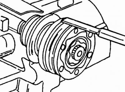
3. Using a mandrel, knock the protective cap off the hinge. The mandrel must be installed one by one at different points around the cap perimeter to remove it evenly. Move the protective cover to the middle of the drive shaft.

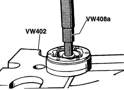
4. Secure the inner joint in a vise, then remove the drive shaft from it. If the drive shaft cannot be removed from the joint, place the joint under a press and, using tools VW 402 and VW 408a, squeeze the drive shaft out of it.
5. Remove the Belleville spring washer from the drive shaft, after noting its position. The washer is splined and the convex side of the washer is on the hinge side.
6. Thoroughly clean the drive shaft before installing a new joint.
7. Install the spring washer onto the shaft so that the convex side of the washer is on the hinge side and the inner splines of the washer are aligned with the splines of the shaft.

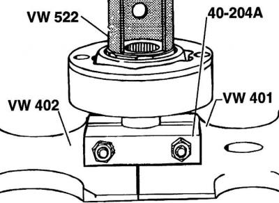
8. Secure the inner CV joint in a soft jaw vise and insert the drive shaft into it. If the shaft does not fit into the joint, press the joint onto the shaft using a press, while the shaft from below must rest on the support.
9. Install a new circlip into the drive shaft groove.
10. Fill the inner joint with 120 grams of grease, putting one half of the grease into the joint on one side and the other half on the other side.
11. Replace the protective cover. Before fastening the protective cover with clamps, use a screwdriver to lift the inner edge of the cover to equalize the air pressure under the cover.

Visitor comments