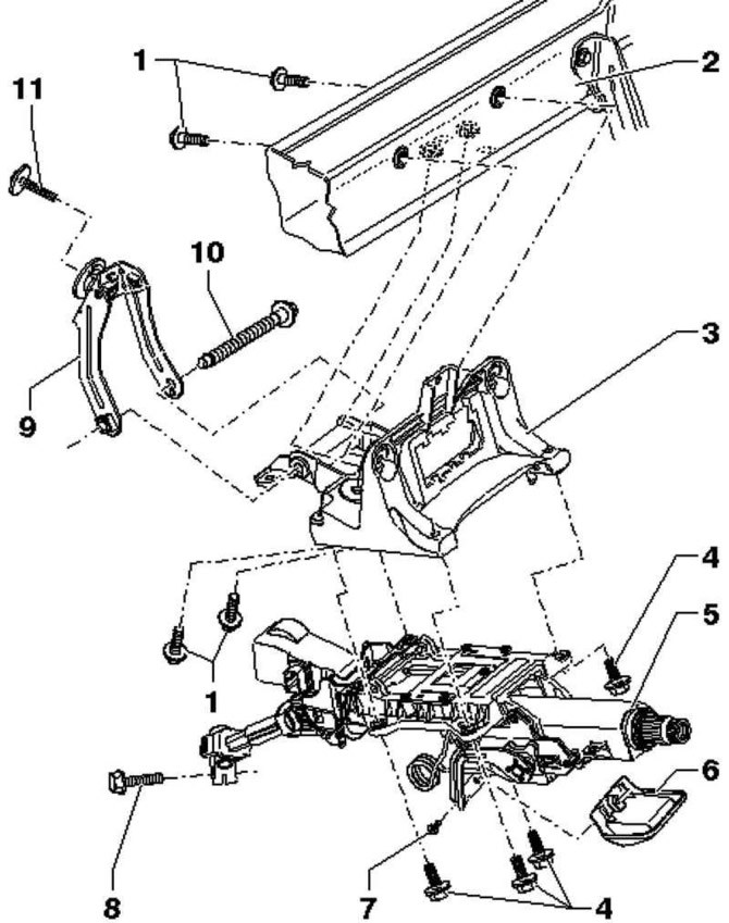
Pic. 5.8. Steering column components: 1 – a bolt with a six-sided head; 2 – a cross beam of a steering column; 3 - support bracket; 4 – a bolt with a six-sided head; 5 - steering column; 6 - handle plate; 7 - bolt; 8 – a bolt with a six-sided head; 9 - damper; 10 – a bolt with a six-sided head; 11 – a bolt with a six-sided head
Note: Welding and straightening work on the bearing and guiding elements of the suspension is not allowed.
Note: Self-locking nuts must always be replaced.
Note: Corroded bolts and nuts must be replaced.
Removing
The steering column is supplied as a spare part assembly only. Repair is not possible.
Note: Before replacing the steering column, always carry out «ELV control unit adaptation».
Attention: Before working on the electrical system and removing the steering wheel, the following conditions must be met.
Attention: Unscrew the negative terminal of the battery.
Note: Wheels must be straight.
Caution: Failure to follow these instructions may result in the failure of the airbag system during subsequent operation.
Set the wheels straight.
Pull the lever under the steering column down.
Tilt the steering column as low as possible and pull out.
Press the lever under the steering column up again.
Remove the airbag from the steering wheel.
Remove the steering wheel.
Remove a facing overlay of the block of understeering switches.
Remove the left trim on the driver's side.
Remove the steering column switch block.
Remove the footwell air deflectors under the steering column.
Disconnect all connectors and negative wires on the steering column.
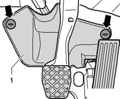
Pic. 5.9. Fastening footwell trim
Unscrew the fixing nuts and remove the lining of the driver's footwell 1 (pic. 5.9).
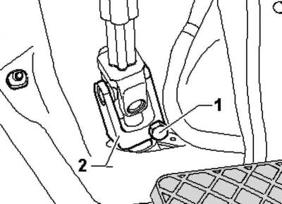
Pic. 5.10. Cardan joint mount
Unscrew the bolt 1 and remove the cardan joint 2 from the steering mechanism (pic. 5.10).
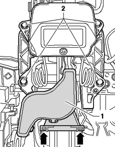
Pic. 5.11. Cable channel under the steering column
Remove the cable channel 1 under the steering column (pic. 5.11).
To do this, slightly raise the tabs and remove the cable channel from the guide on the steering column.
Remove screws 2.
Slightly lower the steering column and carefully remove it upwards.
Attention: Ensure proper handling and transport of the steering column.
Installation
Install the steering column into the mounting tool on the support bracket.
Align the steering column with the support bracket and insert.
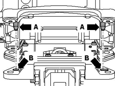
Pic. 5.12. Combination of trunnions and holes
In this case, the trunnions A of the support bracket and the hole B of the steering column must be aligned and insert the trunnions into the holes (pic. 5.12).
This is the only way to ensure the correct installation position of the steering column in relation to the support bracket.
Tighten bolts 2 steering column (pic. 5.11).
Install conduit 1 under the steering column.
The feet should lock into the guide on both sides.
Push universal joint 2 onto steering gear and tighten bolt 1 (pic. 5.10).
Fit trim in footwell 1 and secure with nuts (pic. 5.9).
Connect all plug connectors and negative wires on the steering column.
Install the footwell air deflectors under the steering column.
Establish the block of understeering switches.
Establish a facing overlay of the block of understeering switches.
Install the left trim on the driver's side.
Install the steering wheel.
Install the airbag on the steering wheel.
Tightening moments.
Then carry out a basic adjustment of the steering angle sensor using a tester.

Visitor comments