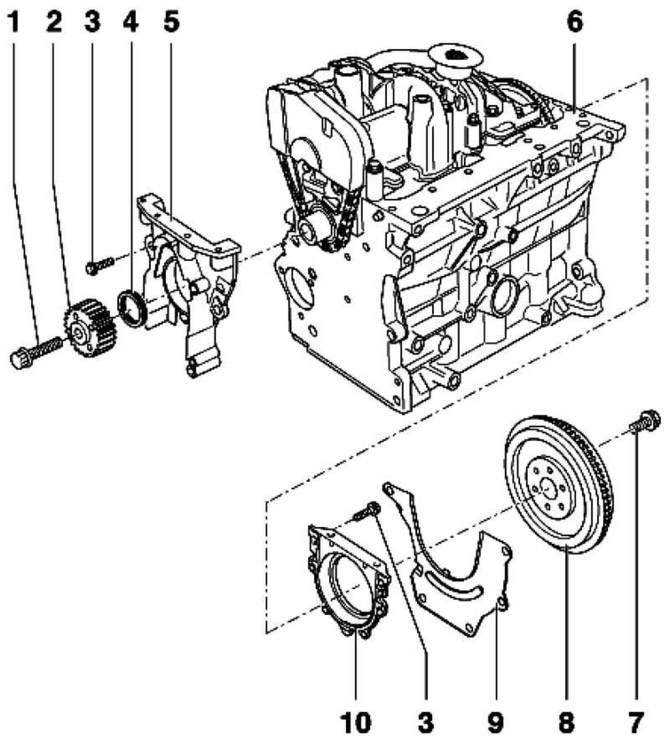
Pic. 2.137. Sealing flanges and flywheel: 1 - bolt 90 Nm + tighten 1/4 rev. (90°); 2 - crankshaft sprocket; 3 - bolt 15 Nm; 4 - stuffing box; 5 - sealing flange; 6 – block of cylinders; 7 - bolt 60 Nm + tighten 1/4 turn. (90°); 8 - flywheel / driven disk; 9 - intermediate plate; 10 - sealing flange with sealing ring
Removing the gland
Remove poly V-belt.
Remove toothed belt
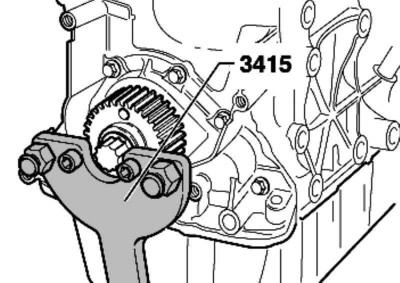
Pic. 2.138. Fixing the crankshaft sprocket
Remove the crankshaft sprocket. To do this, secure the crankshaft gear with a counterhold (pic. 2.138).
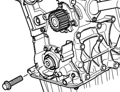
Pic. 2.139. Installing the center bolt
To insert the oil seal remover, screw the central bolt into the crankshaft until it stops by hand (pic. 2.139).
Loosen the inside of the oil seal remover nine turns (about 20 mm) from the outside and secure with a knurled screw.
Lubricate the threaded head of the puller with engine oil, install and, pressing firmly, screw it as far as possible into the oil seal.
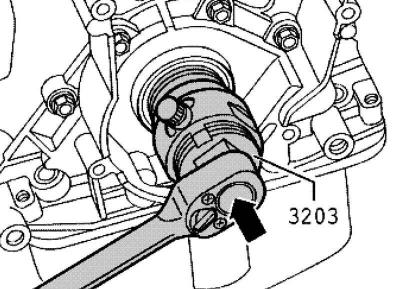
Pic. 2.140. Turning the inside of the puller
Loosen the knurled bolt and turn the inside of the puller against the crankshaft until the oil seal is pulled out (pic. 2.140).
Installing the gland
Wipe off any remaining oil on the crankshaft journal with a clean rag.
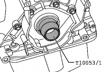
Pic. 2.141. Installing the guide bush
Install the guide bushing on the crankshaft journal (pic. 2.141).
Push the dry oil seal through the guide sleeve onto the crankshaft journal.
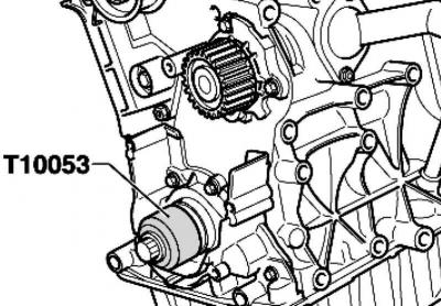
Pic. 2.142. Pressing in the stuffing box
Press in the oil seal using the mounting tool and bolt (M16x1,5x60) all the way (pic. 2.142).
Install the crankshaft gear and secure it with a counterhold (pic. 2.138).
Note: The mating surfaces between the toothed belt drive gear and the crankshaft must be free of oil.
Note: The center bolt must be replaced.
Note: Threads and collar must be free of oil and grease.
Tighten the new bolt to 90 Nm and tighten it 90° (1/4 turn) (turning can be carried out in several stages).
Further installation and assembly is carried out in the reverse order of removal.

Visitor comments