Removing
Remove the engine cover.
Note: The toothed belt may only be installed when the engine is cold, as the position of the tensioning roller mark depends on the engine temperature.
Remove poly V-belt.
Remove the poly V-belt tensioner.
Remove the top part of the timing belt cover.
Remove a reception pipe from an additional heater.
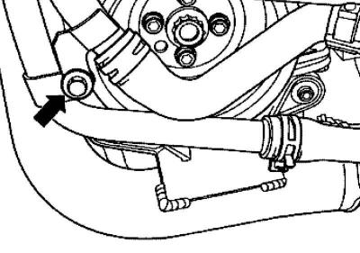
Pic. 2.292. Liquid pipe connecting bolt
Unscrew the connecting bolt of the fluid supply pipe (pic. 2.292).
Remove the charge air pipe between the charge air cooler and turbocharger.
Cover or close open ends carefully.
Remove the vibration damper/pulley.
Remove the lower and middle parts of the toothed belt cover.
Unscrew the fasteners of the fuel lines/tubes of the cooling system on the inlet pipe.
Unscrew the expansion tank of the cooling system and set it aside (hoses remain connected).
Bring the crankshaft to the TDC position of the first cylinder.
Note: Sliding application of oval crankshaft gears. When installing this gear, use the crankshaft retainer to set the pistons to TDC.
Crankshaft gear marks
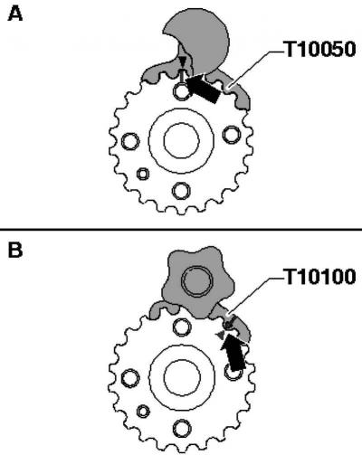
Pic. 2.293. crankshaft gear marks
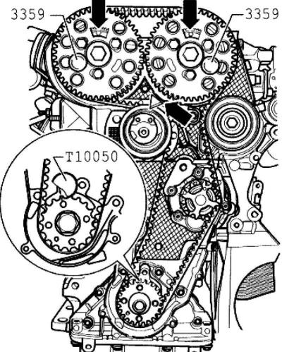
Pic. 2.294. Alignment of the marks on the toothed belt cover and camshaft
Rotate the crankshaft until the mark on the crankshaft gear and the gear sectors of the camshaft gears are at the top. The marks on the timing belt cover and camshaft must match (pic. 2.294).
A - round gear, fix with a crankshaft lock, TDC mark - 12 hours.
B - oval gear, fix the TDC mark - 1 hour with the help of the crankshaft lock.
Note: Secure the crankshaft gear with a crankshaft lock or crankshaft lock. To do this, insert the crankshaft lock from the front side of the gear into its engagement.
Note: The marks on the crankshaft gear and the crankshaft retainer must match. In this case, the pin of the crankshaft retainer must enter the hole in the sealing flange.
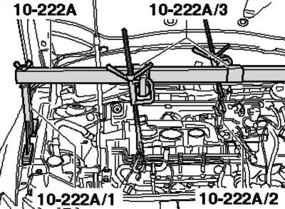
Pic. 2.295. Installing the motor in the mounting position
Establish support console for the engine with supports and raise the engine in mounting position as shown in Figure 2.295.
Remove the engine mount/engine mount mounting bolts and remove the engine mount.
Note: You can only remove the engine mount if the engine is secured using the support-console
Note: The engine mount can only be unscrewed with the power pack mount removed.
Caution: When raising and lowering the engine using the support console, make sure that no components/hoses are damaged, overstretched or torn off.
Raise the engine slightly using the support bracket so that the top two engine support bolts can be unscrewed and removed.
Lower the engine using the support-console so that you can unscrew and remove the lower bolt.
Unscrew the mounting clamp of the air conditioning circuit pipe from the side member.
Note: The engine mount can only be removed with the toothed belt loose.
Note: Mark the running direction of the toothed belt.
Unscrew the fixing bolts 1 and 2 of the camshaft gears until the camshaft gears rotate in the longitudinal grooves.
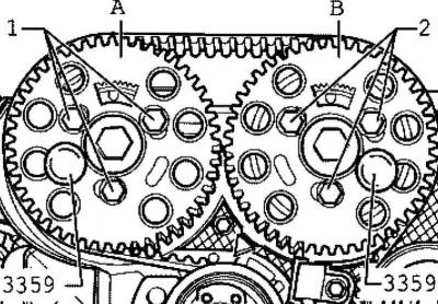
Pic. 2.296. Fixing hubs with pins
Lock the hubs with the locking pin (pic. 2.296).
To do this, insert the locking pins through the free longitudinal grooves into the hole in the cylinder head.
Unscrew the fixing nut of the tension roller.
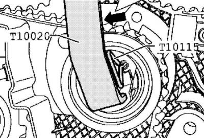
Pic. 2.297. Rotation of the wrench to fix the tension roller
Then turn the wrench anti-clockwise until the toothed belt tensioner is locked with the locking pin (pic. 2.297).
Note: Tensioning and releasing the tension roller can be done with a hex wrench.
Then turn the wrench clockwise until it stops and tighten the fixing nut by hand.
Pull the engine mount up.
Remove the toothed belt first from the coolant pump, then from the remaining gears.
Installation
Secure the camshafts with the locking pin for the injector.
Note: The toothed belt may only be installed when the engine is cold, as the position of the tensioning roller mark depends on the engine temperature.
Note: The tensioner must be secured with a locking pin and on the correct stop.
The crankshaft must be secured with a crankshaft lock or crankshaft lock.
Turn the camshaft gears in the longitudinal grooves clockwise until it stops.
Lay the toothed belt on the crankshaft gear, tension roller and camshaft gears and deflection rollers.
Lay the toothed belt on the coolant pump gear last.
Place the engine mount on top and tighten the bottom mounting bolt.
Raise the engine with the support console so that the tensioner pulley arrow can be seen.
Unscrew the fixing nuts of the tension roller and remove the locking pin.
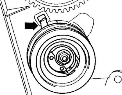
Pic. 2.298. Proper seating of the tension roller
Note: Make sure that the tensioning pulley is properly seated at the rear of the toothed belt cover (pic. 2.298 Note:).
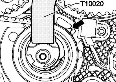
Pic. 2.299. Tension roller rotation
Then rotate the idler with a wrench in the direction of the arrow until the arrow is in the middle of the base plate gap (pic. 2.299).
Make sure that the fastening nuts do not rotate.
Fix the tension roller in this position and tighten the tension roller fixing nut, as follows, with a torque of 20 Nm and tighten by 45° (1/8 turn).
Note: When tightening the fixing nut, the pointer can turn max. 5 mm to the right from the gap of the base plate. This position does not require adjustment, as the toothed belt will be installed correctly during operation.
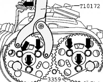
Pic. 2.300. Installing the counter support
Establish a countersupport, as it is shown in drawing 2.300.
Press the counterholder in the direction of the arrow and clamp the camshaft gears.
Tighten the camshaft gear mounting bolts in this position with a torque of 25 Nm.
Remove lock pins and crankshaft retainer or crankshaft retainer.
Make min. 2 revolutions of the crankshaft in the direction of rotation of the engine shaft and again set the first cylinder before the position of the top dead center.
Secure hub A against rotation in the direction of the motor shaft with a locking pin (pic. 2.296).
Hub B must be secured with a locking pin.
The crankshaft is fixed with a crankshaft lock or crankshaft lock.
The arrow of the tension roller is in the middle or max. 5 mm to the right of the base plate spacing.
If the hub B is not fixed, unscrew the fixing bolts 1 of the camshaft gear A.
Hub B must be secured with a locking pin.
Rotate the crankshaft until the camshaft gear hub B is secured with the locking pin (pic. 2.296).
Unscrew the fixing bolts 2 of the camshaft gear B.
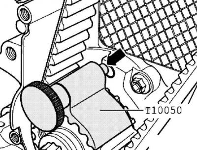
Pic. 2.301. Retainer pin
Rotate the crankshaft slightly against the direction of rotation of the engine shaft until the crankshaft retainer pin is next to the sealing flange hole (pic. 2.301).
Then rotate the crankshaft in the direction of rotation of the engine shaft so that the pin of the retainer engages with the sealing flange.
Establish a countersupport, as it is shown in drawing 2.300. Press the counterholder in the direction of the arrow and clamp the camshaft gears.
Tighten the camshaft gear mounting bolts in this position with a torque of 25 Nm.
Remove lock pins and crankshaft retainer or crankshaft retainer.
Make min. 2 revolutions of the crankshaft in the direction of rotation of the engine shaft and again set the first cylinder before the position of the top dead center.
Repeat control.
Tighten both upper engine clamp bolts to 40 Nm + 1/2 rev. (180°).
Lower the engine using the support-console
Tighten the lower engine clamp bolt to 40 Nm + 1/2 rev. (180°).
Establish the lower and average parts of a cover of a gear belt.
Install vibration damper/belt drive pulley (replace mounting bolts). Tightening torque 10 Nm + tighten by 90° (1/4 turn).
Note: All engine mount bolts must be tightened to the specified torque before installing the powertrain mount.
Install pillow engine/body (replace mounting bolts).
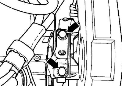
Pic. 2.96. Fastening of an arm of the top support of the engine
Screw engine mount to engine mount, use support console to access parts (pic. 2.96). Tightening torque 60 Nm + tighten by 90° (1/4 turn).
Establish the top part of a cover of a gear belt.
Install the V-ribbed belt tensioner tightening torque 25 Nm
Install poly V-belt.
Further installation is carried out in the reverse order. In doing so, the following must be taken into account
Check the tightness of the fuel hoses.
Do not interchange fuel supply and return lines (fuel return line blue or marked in blue, fuel supply line black).
When installing the charge air pipes, make sure that the fasteners fit securely.
Install the fender.
Install a noise screen.

Visitor comments