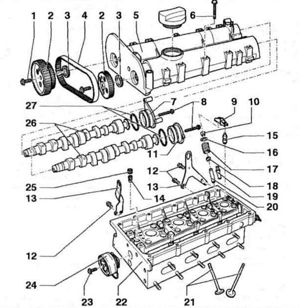
Pic. 4.11 a. Elements of the gas distribution mechanism:
1, 6, 8, 12, 23 - Bolts; 2 - Pulleys of camshafts; 3 - Oil seals; | 4 - Auxiliary timing belt; 5 - Camshaft housing; 7 - Gland cover / holder of the ignition coil; 9 - Roller rocker; 10 - Crackers; 11 - stuffing box cover; 13 - Lifting eye; 14 - bypass valve; 15 - Pusher; 16 - Upper spring plate; 17 - Valve spring; 18 - Valve stem seal; 19 - Valve guide with collar; 20 - valve guide; 21 - Valves; 22 - Cylinder head; 24 - Tension roller; 25 - Cork; 26 - Camshafts; 27 - O-rings.
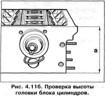
Checking the height of the cylinder head
Cylinder head height: 108.25 mm.
Checking the height of the cylinder head is shown in fig. 4.11 b.
Axial clearance check
Check of an axial backlash of a camshaft by means of the indicator is shown on fig. 4.11 c.
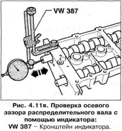
Permissible axial clearance: 0.40 mm.
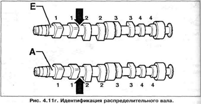
Camshaft identification
Intake camshaft E: 036AC.
Exhaust camshaft A: 036AA.
Camshaft identification is shown in fig. 4.11
Valve timing at 1 mm valve lift
| Inlet valve opens after TDC | 19.1° |
| Inlet valve closes after BDC | 15.1° |
| Exhaust valve opens before BDC | 20.2° |
| Exhaust valve closes before TDC | 15.3° |
Valve dimensions
Valve dimensions are shown in fig. 4.11 d.
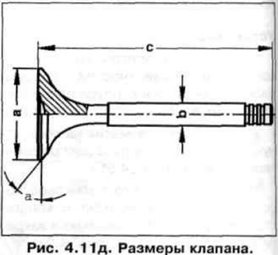
| Dimensions, mm | Inlet valve | Exhaust valve |
| Diameter «A» | 29.5 | 26.0 |
| Diameter «b» | 5.973 | 5.953 |
| Valve length «With» | 100.9 | 100.5 |
| Corner «A», ° | 45 | 45 |

Visitor comments