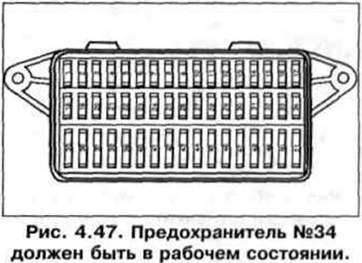
2. Fuse number 34 must be in working order (pic. 4.47).
3. Connect a multimeter to check the voltage using wires from VAG 1594 to pins 2 and 4 of the wiring connector (pic. 4.48).
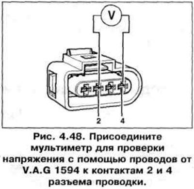
4. Turn on the ignition. Specification value: 11 V minimum.
5. Turn off the ignition.
6. If there is no voltage, remove the cover on the left in the engine compartment and connect the VAG 1598/31 tester to the engine control unit wiring harness (on the left side of the engine compartment) (rice. 4.32). The control unit must remain disconnected.
7. Check the wire between pin 2 of the 4-pin harness connector and the relay base for an open circuit (pic. 4.49). Specification resistance: 1.5 Ohm.
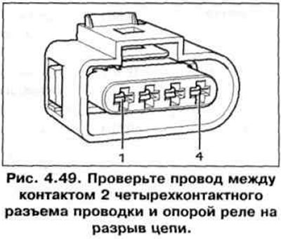
8. Check the wire between pin 4 of the four-pin harness connector and «weight» to break the chain. Specification resistance: 1.5 Ohm.
Activation check
9. Remove the engine cover (rice. 4.44).
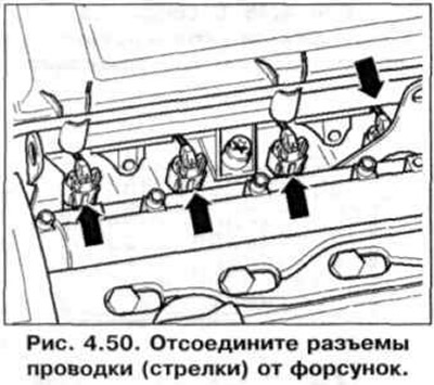
10. Disconnect wiring connectors (arrows) from injectors (pic. 4.50).
10. Connect the diode tester VAG 1527 using wires from VAG 1594 to pins 1 and 4 (exit 1) and to pins 2 and 3 (exit 1) disconnected connector (pic. 4.48).
11. Start the engine with a starter and check the ignition signal from the engine control unit. The tester light should flash.
12. Turn off the ignition.
13. If the tester light flashes and there is voltage between pins 2 and 3. replace the ignition coil.
14. If the tester light does not flash. check wiring.
Wire Check
15. Remove the cover on the left in the engine compartment and connect the VAG 1598/31 tester to the engine control unit wiring harness (rice. 4.32). Check the wires between the tester and the connector for continuity: pin 1 + socket 102, pin 2 + socket 103. Wire resistance: max. 1.5 ohm.
16. In addition check up short circuit one on another wires.
Specification resistance: ∞ Ohm.
17. If no faults are found in the wiring and there is voltage between pins 2 and 4, replace the engine control unit.
Checking the resistance of the secondary coil
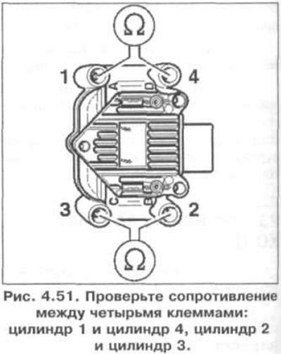
18. Check the resistance between the four terminals: cylinder 1 and cylinder 4, cylinder 2 and cylinder 3 (pic. 4.51). Specification resistance: 4-6 kOhm (at 20°C).
19. If resistance does not correspond required, replace the ignition coil.

Visitor comments