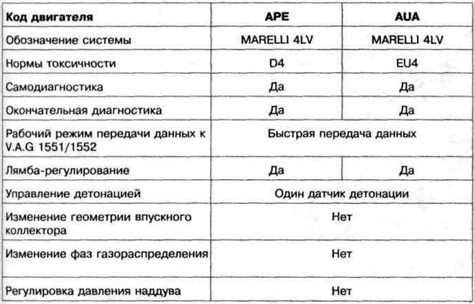
Table 4.2. Technical characteristics of the fuel injection and ignition control system
The arrangement of elements of system of injection of fuel is shown in fig. 4.24 a, b. The intake manifold is shown in fig. 4.25. The high pressure fuel line with injectors is shown in fig. 4.26. The disassembled air filter is shown in fig. 4.27. The arrangement of elements of system of ignition is shown in fig. 4.28. The adjustment data of the ignition system and the marking of the spark plugs are given in Table 4.3.
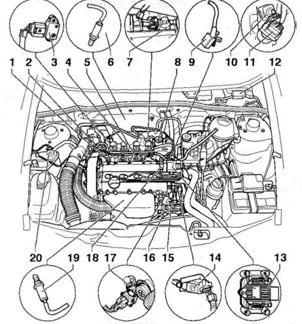
Pic. 4.24 a. Location of elements of the fuel injection system:
1 - Fuel pressure regulator; 2 - Oxygen sensor wiring connector (after catalyst); 3 - Intake manifold pressure sensor with inlet air temperature sensor; 4 - Intake manifold; 5 - Nozzle; 6 - Oxygen sensor (after catalyst); 7 - Knock sensor; 8 - Throttle valve block; 9 - Crankshaft speed sensor; 10 - Brake pedal sensor; 11 - Stoplight switch; 12 - Engine control unit; 13 - Ignition coil; 14 - Three-pin wiring connector for the crankshaft speed sensor; 15 - Exhaust gas recirculation valve together with a potentiometer for exhaust gas recirculation; 16 - Four- and six-pin wiring connectors for the oxygen sensor and oxygen sensor heater before the catalyst; 17 - Coolant temperature sensor; 18 - Hall sensor; 19 - Oxygen sensor in front of the catalyst; 20 - Solenoid valve for activated carbon filter.
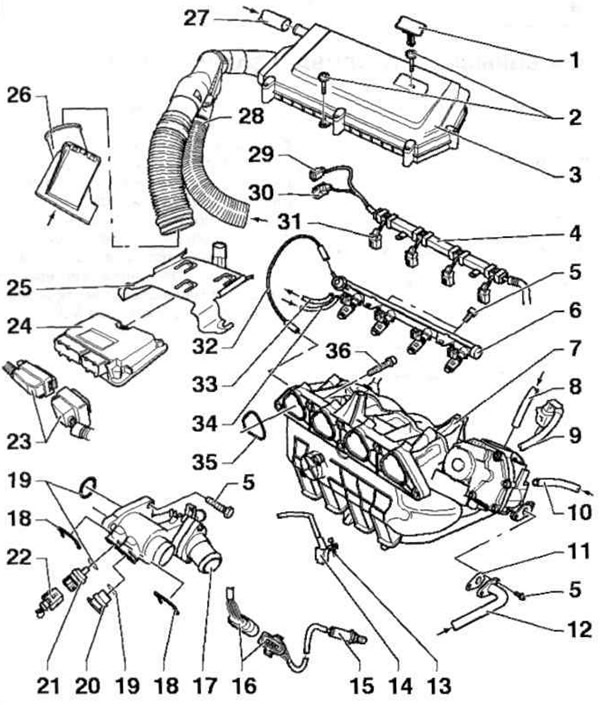
Pic. 4.24 b. Location of elements of the fuel injection and ignition system:
1, 20 - Plugs; 2, 5, 13, 36 - Bolts; 3 - Air filter; 4 - Wire harness guide; 6 - High pressure fuel line with nozzles; 7 - Intake manifold; 8 - From the solenoid valve of the activated carbon filter; 9 - Wiring connector, nine-pin, from the throttle body; 10 - From the vacuum brake booster; 11 - Gasket; 12 - From the exhaust gas recirculation valve; 14 - Crankshaft speed sensor; 15 - Oxygen sensor in front of the catalyst; 16 - Four- and six-pin wiring connectors for the oxygen sensor and oxygen sensor heater before the catalyst; 17 - Thermostat housing; 18 - Retainer; 19 - O-ring; 21 - Coolant temperature sensor; 22 - Wiring connector, four-pin, from the coolant temperature sensor; 23 - Connector wiring engine control unit; 24 - Engine control unit; 25 - Support; 26 - Adapter for intake duct; 27 - Crankcase ventilation tube; 28 - Heating of incoming air; 29 - Wiring connector, four-pin, from the intake manifold pressure sensor to the intake air temperature sensor; 30 - Wiring connector, two-pin, from the knock sensor; 31 - Wiring connector, two-pin, from injectors; 32 - Vacuum tube; 33 - Drain fuel line; 34 - Delivery fuel line; 35 - Oil seal.
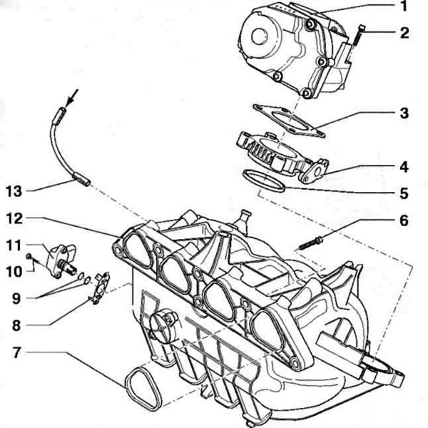
Pic. 4.25. Intake manifold:
1 - Throttle valve block; 2, 6, 10 - Bolts; 3 - Gasket; 4 - Connecting flange; 5, 7 - Oil seals; 8 - Guide plate; 9 - O-rings; 11 - Intake manifold pressure sensor with inlet air temperature sensor; 12 - Intake manifold; 13 - Vacuum tube.
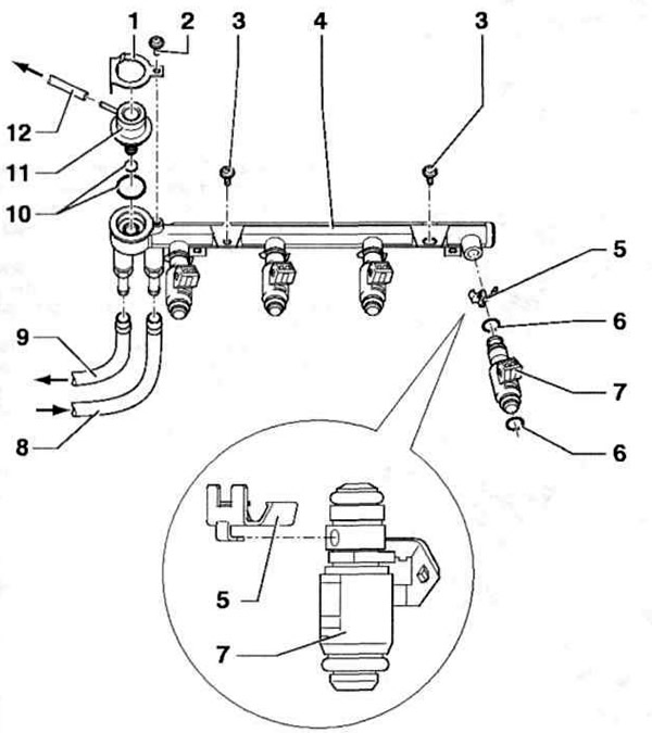
Pic. 4.26. High pressure fuel line with injectors:
1 - Mounting plate; 2, 3 - Bolts; 4 - High pressure fuel line; 5 - Retainer; 6, 10 - O-rings; 7 - Nozzles; 8 - Delivery fuel line; 9 - Drain fuel line; 11 - Fuel pressure regulator; 12 - Vacuum tube.
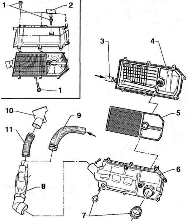
Pic. 4.27. Air filter disassembled:
1 - Bolt; 2 - Cork; 3 - Crankcase ventilation tube; 4 - Upper part of the air filter; 5 - Filter element; 6 - The lower part of the air filter; 7 - Seals; 8 - Air intake housing with damper; 9 - Heated air supply pipe; 10 - Adapter; 11 - Connecting pipe.
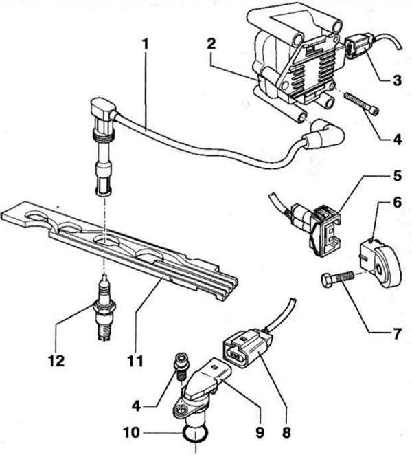
Pic. 4.28. The location of the elements of the ignition system:
1 - High voltage wire; 2 - Ignition coil (A - cylinder 1, B - cylinder 2, C - cylinder 3, D - cylinder 4); 3 - Ignition coil wiring connector; 4, 7 - Bolts; 5 - Knock sensor wiring connector; 6 - Knock sensor; 8 - Hall sensor wiring connector; 9 - Hall sensor; 10 - O-ring; 11 - Guide plate of high-voltage wires; 12 - Spark plug.
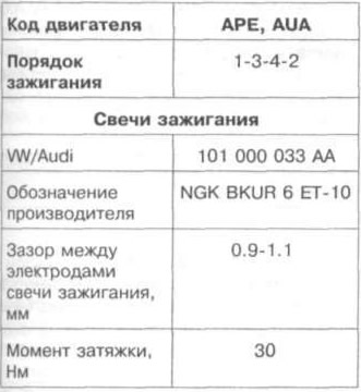
Table 4.3. Adjustment data of the ignition system and marking of spark plugs

Visitor comments