Removing the engine
For further work, you must disconnect the wire «masses» battery.
Therefore, you must first check whether a radio with coding is installed in the car. In this case, you must first request a security code.
1. Remove the acoustic cover.
2. Place the front carrier in the service position.
3. The engine is removed together with the gearbox upwards.
4. Disconnect the ground wire from the battery with the ignition off.
5. After installing the engine, it is necessary to re-install and in the same places all the plastic clamps removed or cut off during dismantling.
6. Remove the air filter housing.
7. Remove the battery together with the mounting platform.
8. Open and close the coolant expansion tank cap again to relieve pressure in the cooling system.
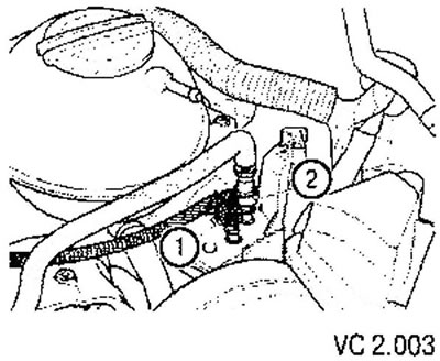
9. Disconnect the hose from the solenoid valve (1) activated carbon absorber (N80) at the intake manifold.
Caution: The fuel supply line is under pressure! Wear safety goggles and gloves to avoid injury and skin contact with fuel. Before disconnecting the elements of the system, the connection point must be wrapped with rags. The pressure must then be relieved by carefully disconnecting the hose.
10. Disconnect the fuel supply line (2) and hose of the fuel vapor absorption system (1). To do this, press the release button for the quick coupling of the hoses.
11. To prevent contamination from entering the fuel system, plug the openings of the fuel lines.
12. Disconnect the vacuum and ventilation hoses from the engine.
13. Disconnect the plug from the radiator fan.
14. Remove the front wall of the plenum box.
15. Disconnect the block wiring harness connector from the engine control unit, for which perform the following steps.
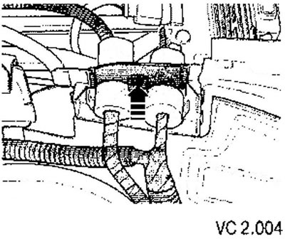
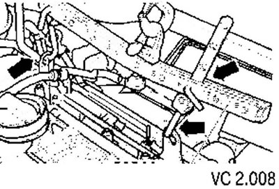
- Unlock engine wiring harness entry (arrow) and lift up.
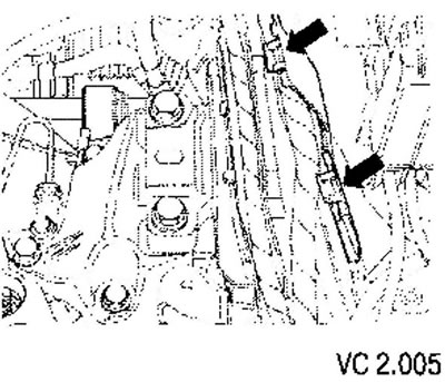
- Open all wiring clamps on the side member (arrows).
- Remove the wiring harness from the engine control unit.
- Secure the wiring harness to the engine with a cable tie.
- Disconnect all other wires from the engine that need to be disconnected and set them aside.
16. Unscrew the front exhaust pipe from the exhaust manifold.
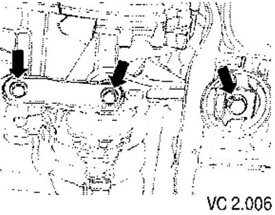
17. Unscrew the oscillating support (arrows).
18. Unscrew the gear selector link from the gearbox.
19. Disconnect the quick connector (IN) pipes of the hydraulic clutch drive from the working cylinder of the clutch hydraulic drive, for which pull the bracket (A).
20. Pull out the handset (IN) from the holder (WITH).
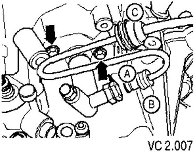
After disconnecting the hydraulic drive, do not press the clutch pedal.
21. Drain coolant.
22. Disconnect the coolant hoses from the engine.
For vehicles with air conditioning
23. Remove poly V-belt.
24. Unscrew the air conditioner compressor, but do not open the circuit containing the refrigerant.
25. Attach the air conditioner compressor to the radiator frame.
26. Check that the hoses are not pinched.
Continued job description for all vehicles
27. Disconnect the right and left drive shafts from the gearbox and tie them up.
28. Fix the traverse and slightly raise the engine with a hoist (winches).
29. Unscrew the filler neck of the windshield washer reservoir.
30. Unscrew the expansion tank of the cooling system and take it to the side without disconnecting the hoses.
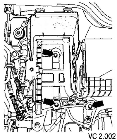
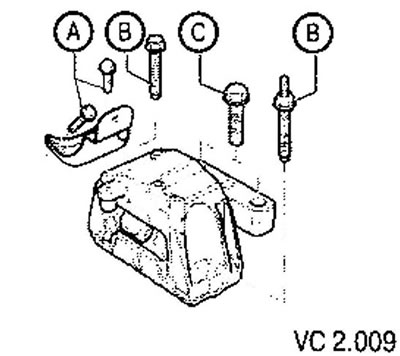
31. Unscrew the screws (A), (IN) And (WITH) from the power unit support bracket on the poly V-belt pulley side and remove the power unit support.
32. Unscrew the power unit from the gearbox support (arrows) and take it off.
33. Carefully lift the machine up.
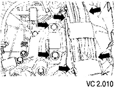
Raise the power unit carefully to avoid damage to the body.
Engine installation
Installation is carried out in the reverse order, observing the instructions below.
Attention: when performing installation work, especially in the engine compartment due to its dense layout, the following rules must be observed.
- Highways of all types (fuel, hydraulic, fuel vapor recovery systems, coolant, coolant, brake fluid, vacuum) and wires should be routed in the original factory order (using appropriate fasteners).
- To avoid damage to hoses, pipes or wires, make sure that there is enough space when working on all moving or hot parts.
1. Check the clutch release bearing for wear and replace if necessary.
2. Apply a light coat of grease to the clutch release pad, guide bushing and input shaft splines (G OO0100).
3. Check the presence of centering bushings that determine the relative position of the engine and gearbox. If bushings are missing, they must be installed in the cylinder block.
4. Install the intermediate plate on the centering sleeves of the motor flange (arrows).
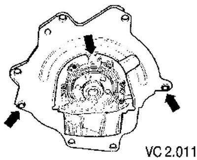
5. When lowering the machine, ensure that there is sufficient space for the drive shafts.
6. Fix the power unit on the supports.
The accessory support bolts are malleable bolts and must be replaced.
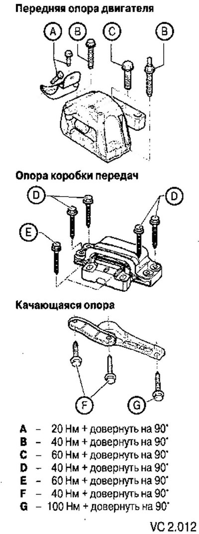
7. Install drive shafts.
Cars with air conditioning
8. Install the air conditioner compressor.
9. Install poly V-belt.
Continued job description for all vehicles
10. Connect all electrical connectors and secure the wiring in the engine compartment.
11. Connect the tube (IN) to the quick coupling of the hydraulic clutch by securely snapping the clip (A).
12. Remove air from the hydraulic clutch.
13. To establish a scene of the selector of transfers.
14. Install soundproof casing.
15. Fill in coolant.
Engine code BCA
16. Install the air filter housing.
17. Adapt the engine control unit to the throttle control unit and to the EGR valve-H18.
Engine code BUD
18. Install the air filter housing.
Continued job description for all vehicles
19. Carry out testing of automotive systems.
20. Carry out a test drive and interrogate the fault memory.
Tightening torques
| Threaded connection | Torque | |
| Bolts, nuts | M6 | 10 Nm |
| Bolts, nuts | M8 | 20 Nm |
| Bolts, nuts | M10 | 45 Nm |
| Bolts, nuts | M12 | 60 Nm |
| downpipe manifold | 40 Nm |

Visitor comments