Installation can also be carried out in another way, provided that the following installation conditions are met, which are described in the description of installation using a special tool.
- Maintaining centering when installing the cover.
- Ensuring the parallelism of the cover of the mating plane of the block.
- Label match (A) And (IN), ensuring the correct position of the ring gear relative to the cover.
- Preliminary alignment of the outer edges of the ring gear and cover.
The installation principle is clear from the following text.
Attention!
- The cover with a PTFE collar has a protective ring for sealing edges. This ring should not be removed before installation, because. during installation, it will play the role of a mounting sleeve.
- After being removed from the packaging, the lid and ring gear must not be separated from each other and rotated relative to each other.
- The correct mounting position of the ring gear is ensured by the fixture lock (Т10134).
- The bonnet and lip seal form a single unit and should only be replaced as an assembly with the ring gear.
- Correct mounting position of fixture (Т10134) provided by a dowel pin that must fit into a corresponding hole in the crankshaft.
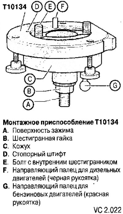
A - Installing the rear oil seal with ring gear on the mounting tool
1. Unscrew the hexagon nut (IN) almost to the clamping surface (A) lead screw (see fig. VC2.022).
2. Install fixture (Т10134) clamping surface (A) lead screw in a vise.
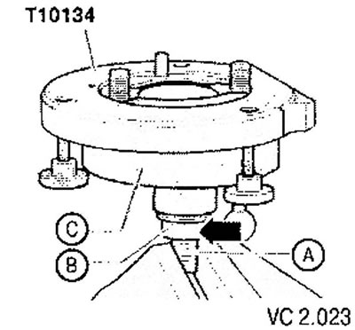
3. Pressing on the body (WITH), slide it down so that it rests on the hex nut (8) (arrow).
4. Fix the inside of the fixture flush with the body with a nut.
5. Remove the safety clip from the new cover (arrow).
Attention! Do not remove or rotate the ring gear from the cover.
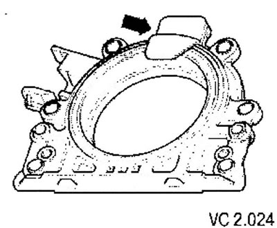
6. Place the lid on a clean, flat surface on the front (outdoor) side down.
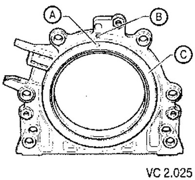
7. Press on the support ring (A) in the direction of the arrow down until it rests on a level surface.
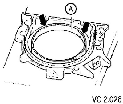
8. The top edge of the ring gear and the front edge of the cover must be at the same level (arrows).
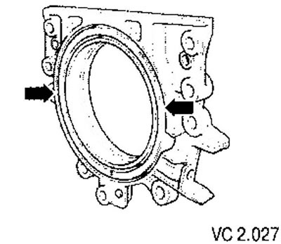
9. Place the front side of the cover on the mounting tool (Т10134) so that the pin (IN) entered the hole (A) tooth crown. In this case, the cover must completely, over the entire plane, adjoin to the mounting device.
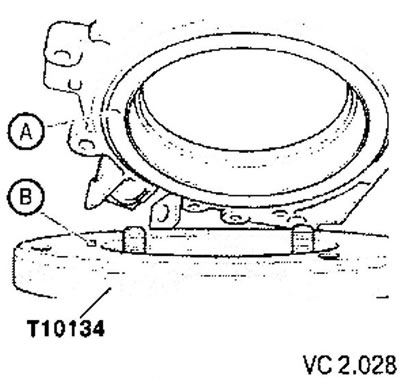
10. Press the cover and support ring (IN) while tightening the three bolts (A) on the mounting surface (Т10134), so that the locking pin cannot slip out of the hole in the ring gear. When installing the cover, the ring gear must remain fixed in the assembly tool at all times.
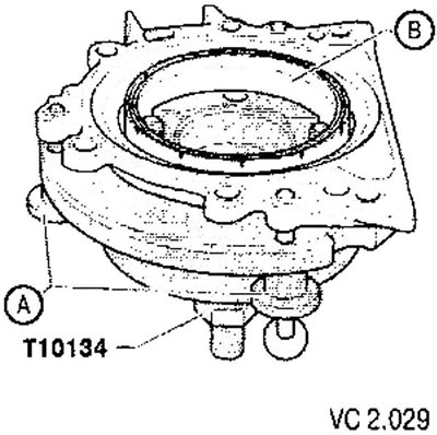
B - Installing the mounting tool with the rear cover of the cylinder block on the end of the crankshaft
- The crankshaft flange must be free of oil residues (degrease).
- Set the engine to TDC of cylinder #1.
- Unscrew the hex nut (IN) to the top end of the lead screw.
1. Press the lead screw of the mounting tool (Т10134) in the direction of the arrow until the hex nut (IN) won't stick to the body (A).
2. Attach the cover with the fixture to the mating surface of the cylinder block.
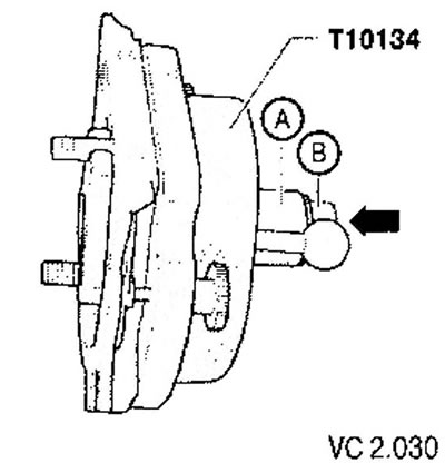
3. Attach fixture (Т10134) on the crankshaft flange with hexagon socket screws (A).
Attention! hex socket bolts (A) screw into the crankshaft flange by about 5 thread pitches.
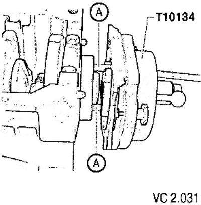
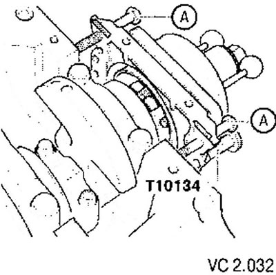
4. Screw in two screws M6x35 mm (A) to enter cover 8 cylinder block.
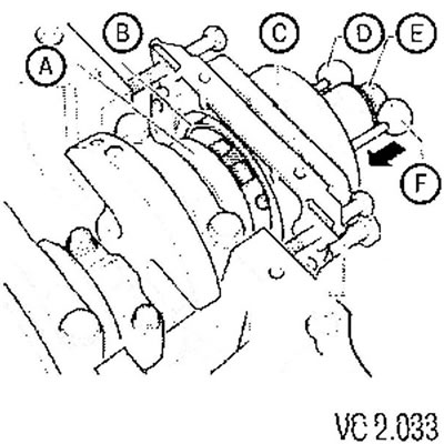
C - Attaching the mounting tool to the crankshaft flange
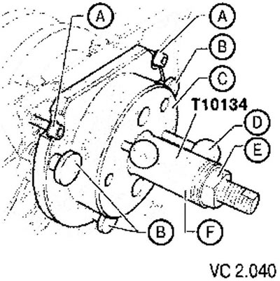
1. Manually move the case (WITH) in the direction of the arrow until the support ring (IN) will not touch the crankshaft flange (A).
Insert guide pin for petrol engines (red handle) (F) into the hole in the crankshaft.
This will fix the final mounting position of the ring gear.
Attention! Guide pin for diesel engines (lever (D)) insert into the threaded hole of the crankshaft is unacceptable.
2. Tighten both hexagon socket screws of the assembly tool by hand.
3. Tighten the hex nut (E) by hand on the lead screw so that it rests against the body of the mounting tool (WITH).
D - Pressing the ring gear onto the crankshaft using the mounting tool
Tighten the tool hex nut (Т10134) torque 35 Nm. In this case, after tightening the hex nut, there should still be a small gap between the cylinder block and the flange.
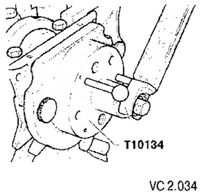
E - Checking the installation position of the ring gear on the crankshaft
1. Unscrew the hexagon nut (E) to the top end of the lead screw.
2. Remove two screws (A) from the cylinder block.
3. Remove the three knurled screws (IN) from the sealing flange.
4. Remove the mounting tool (Т10134).
5. Remove protective ring.
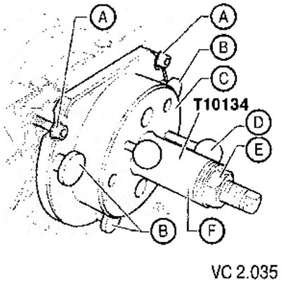
The ring gear assumes an exact installation position on the crankshaft when between the crankshaft flange (A) and toothed rim (IN) there is a distance (A) 0.5 mm.
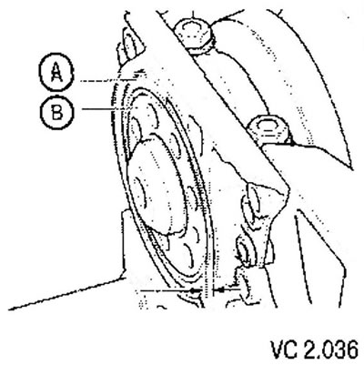
6. Install the caliper on the crankshaft flange.
7. Measure distance (A) between the crankshaft flange and the ring gear.
If the distance (A) too little, then the ring gear needs to be repressed.
If the distance (A) reached, then install new screws securing the rear cover of the cylinder block and tighten them alternately crosswise to a torque of 15 Nm.
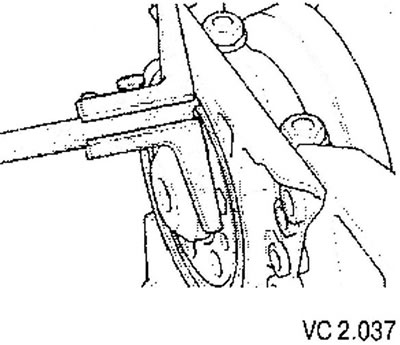
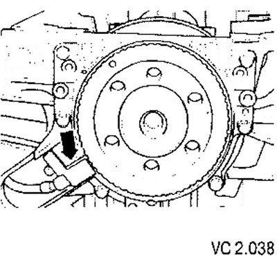
8. Install engine speed sender G28 (arrow) and tighten the fixing screw to 5 Nm.
9. Install the oil pan.
10. Install intermediate plate.
11. Install flywheel with new bolts. Tighten screws to 60 Nm + 1/4 turn (90°).
F - Final pressing of the ring gear
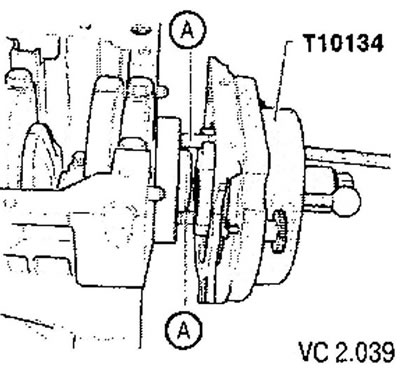
1. Attach fixture (710134) on the crankshaft flange with hexagon socket screws (A).
2. Tighten hexagon socket screws by hand.
3. Fixture (Т10134) move by hand to the crankshaft cover.
4. Tighten the hex nut (E) by hand on the lead screw until it stops against the body of the mounting device (WITH).
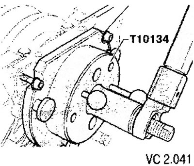
5. Tighten the hex nut of the tool (Т10134) torque 40 Nm.
6. Again check the correct position of the ring gear on the crankshaft.
If the distance (A) too small, tighten the hexagon nut of the tool (Т10134) torque 45 Nm.
7. Again check the correct position of the ring gear on the crankshaft.

Visitor comments