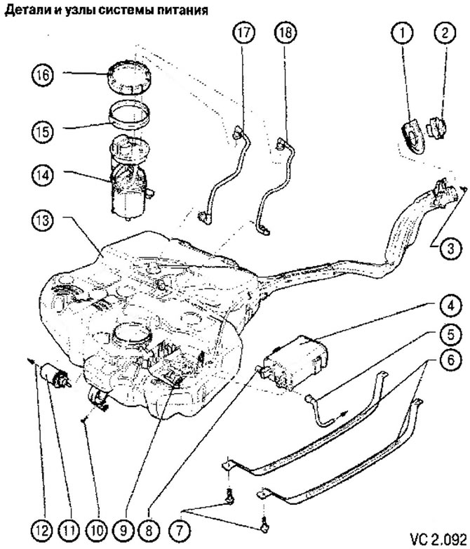
Details and components of the power system:
1. Filler cap
2. Filler cap
3. Filler screw
4. Activated carbon fuel vapor absorber
5. Ventilation hose connected to the absorber solenoid valve
6. Fuel tank support straps
7. Fuel tank screws: 20 Nm
8. Ventilation pipe of the hose connecting the absorber to the fuel tank
9. Pressure reducing valve
10. Fuel filter mounting screw
11. Fuel filter:
- installation position: the arrow indicates the direction of flow
12. Fuel filter outlet
13. Fuel tank
14. Fuel supply module with fuel level sensor (G)
15. Shaft seal for fuel delivery module
16. Snap ring: 80 Nm
17. Supply line (black color)
18. Return line (of blue color)

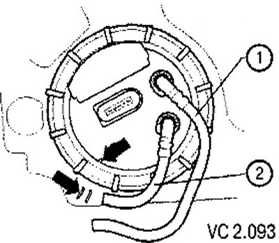
Mounting position of the fuel delivery module flange:
1. Fuel return line (blue or blue label)
2. Pressure fuel line (black)

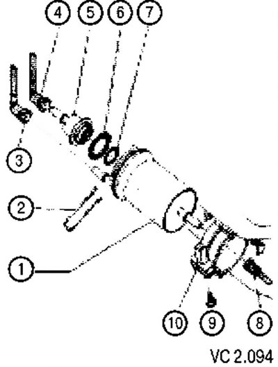
Parts and assemblies of the fuel filter with mating elements (pic. VC2.094):
1. Fuel filter:
- the direction of the fuel flow is marked with an arrow;
- when connecting pipelines, do not mix them up;
- installation position: the pin on the filter housing must fit into the groove of the guide on the filter bracket.
2. Mounting bracket for fuel pressure regulator.
3. Black fuel supply line (from fuel tank):
- to disconnect, press the connector lock.
4. Blue fuel return line (to the fuel tank):
- to disconnect, press the connector lock.
5. Fuel pressure regulator (0.4 MPa (4 bars).
6. Gasket:
- when assembling, replace with a new one.
7. O-ring:
- when assembling, replace with a new one.
8. Black fuel supply line (to the engine):
- to disconnect, press the fitting lock.
9. Coupling bolt 3 Nm.
10. Fuel filter bracket:
- attached to the fuel tank.

Visitor comments