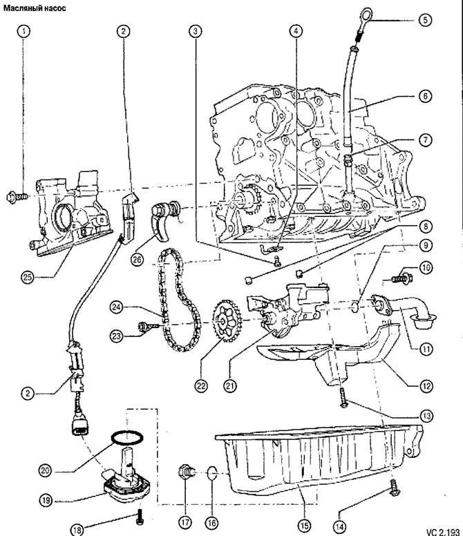
List of parts of the lubrication system with technological notes on repair to Figure VC2.193:
1. Screw of fastening of a forward cover of the block of cylinders: 15 Nm.
2. Bracket for oil level and temperature sensor wiring harness (G2S6).
3. Screw for fastening the piston oil cooling nozzle with a pressure reducing valve: 27 Nm:
- actuation pressure: 0.13-0.16 MPa (1.3-1.6 bar);
- Applies to BGU engines only.
4. Piston oil cooling nozzle:
- Applies to BGU engines only.
5. Oil dipstick:
- the oil level must not be higher than the max mark!
6. Top of dipstick guide tube:
- Remove when draining oil.
7. Lower part of the guide tube.
8. Centering sleeves.
9. O-ring:
- when assembling, replace with a new one.
10. Oil receiver mounting screw: 15 Nm.
11. Oil receiver:
- if necessary, clean the filter mesh.
12. Oil bath dampener in the oil sump.
13. Screw for fastening the oil bath stabilizer in the oil sump: 15 Nm.
14. Oil pan fixing screw: 15 Nm.
15. Oil pan.
16. O-ring for oil drain plug, non-removable.
17. Oil drain screw: 30 Nm:
- Replace the plug complete with sealing ring.
18. Screw for fastening the oil level and temperature sensor (G266):10Hm.
19. Oil level and temperature sensor (G266).
20. O-ring:
- when assembling, replace with a new one.
21. Oil pump:
- with pressure reducing valve 1.2 MPa (12 bar);
- before installation, check the presence of centering bushings that determine the relative position of the oil pump and the cylinder block;
- if there are scratches or scuffs on the working surfaces and gears, replace the entire pump.
22. Chain drive sprocket.
23. Chain sprocket screw: 20 Nm, then tighten by 90°.
24. Chain.
25. Front cover of the cylinder block.
26. Chain tensioner with shoe: 15 Nm:
- compress the spring before installing.

Visitor comments