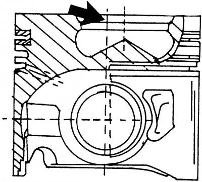
Pic. 420. Piston sections. The arrow shows the combustion chamber

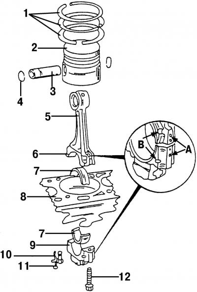
Pic. 421. Type of piston and connecting rod: 1 - piston rings; 2 - piston; 3 - piston pin; 4 - retaining ring; 5 - connecting rod; 6 - locating pin; 7 - bearing shell; 8 - cylinder block; 9 - connecting rod bearing cover; 10 - oil spray nozzle; 11 - bolt, 10 Nm; 12 - connecting rod bolt
The details of the connecting rod and piston group are shown in fig. 421. The section of the piston of the TDI diesel engine is shown in fig. 420. The shape of the combustion chamber type «Omega» (bucket). To remove the pistons, the engine and cylinder head must be dismantled.

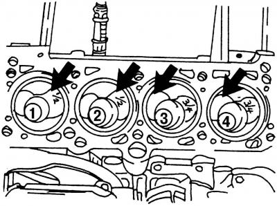
Pic. 422. View of the top of the engine. The arrows show the large inlet valve recesses, which are positioned differently on pistons #1 and 2, #3 and 4
After removing the cylinder head, the pistons look as shown in fig. 422. Each piston has a larger intake valve notch, however, they are not all on the same side. The piston recesses for cylinders #1 and 2 are closer to the flywheel side, the piston recesses for cylinders #3 and 4 are closer to the pulley side. For this reason, new pistons are marked 1/2 or 3/4 so you know which cylinders they can fit into. If you want to remove the pistons, then before that you should mark their position by putting the cylinder numbers on them. Incorrect piston installation can damage the engine.

Visitor comments