Valve springs and valve guides
To fully inspect the valve springs, a special spring test tool should be used. If not, then install the springs in a row on a smooth surface so that the closed knurling is at the bottom. Place a steel angle next to the spring and measure the gap between the top of the spring and the angle. The gap should not be more than 2.0 mm. Otherwise, the spring is skewed.
Valve guides
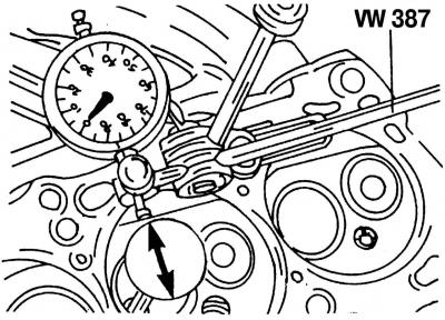
Pic. 38. Checking the runout of the valve stem inside the guide sleeve using the measuring device VW387
The control of the runout of the valve stem inside the guide sleeve is carried out using the VW387 measuring device, dial indicator (pic. 38).
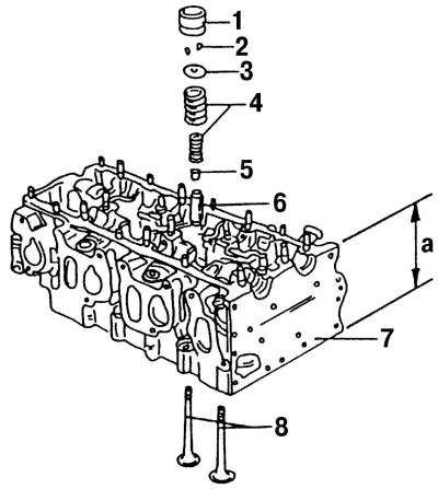
Pic. 37. Details of the valve drive mechanism: 1 - hydraulic pusher; 2 - valve stem halves (crackers); 3 - upper plate of the valve spring; 4 - valve springs; 5 - oil deflector cap; 6 - valve guide sleeve; 7 - cylinder head; 8 - valves; a - cylinder head height
Rock the valve disc in the upper part back and forth and check the readings of the dial indicator. If it shows more than 1.0 mm on the intake valves and more than 1.3 mm on the exhaust valves, then the valve guide needs to be replaced. You should also check the general condition of the cylinder head before replacing the valve guides. A cylinder head with small scratches between the valve seats or between the valve seat and the threads of the spark plug hole can be reground and reused, provided that the scratches do not exceed 0.5 mm in width. After regrinding the cylinder head, the value a (pic. 37) must be at least 139.50 mm. This is the minimum size. The nominal height dimension of the cylinder head is (140±0,1) mm. Measurements should be carried out either with a caliper or a measuring ruler, placing the cylinder head on a flat surface.
- put the cylinder head on the press table to remove the valve guide;
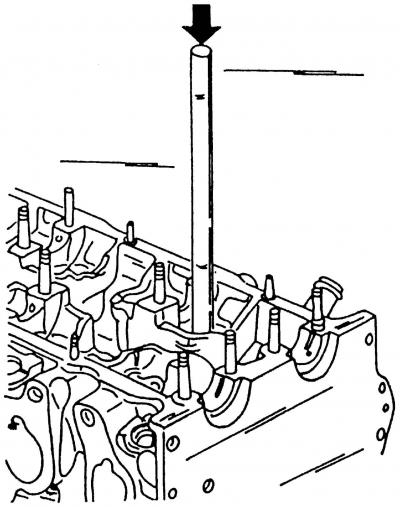
Pic. 39. Pressing out the valve guide. New bushings are pressed in from the same side
- valve guides are removed by pressing them out from the side of the camshafts of the cylinder head (pic. 39) using a puncher.
The cylinder head can be heated to facilitate this work. On the punch, you need to screw the pin, which fits in size to the inside of the valve guide:
- when replacing the valve guide, the valve itself is also changed. Then you need to regrind the valve seats;
- lubricate new valve guides with engine oil before installation and press them from the side of the camshafts into the cold cylinder head so that the shoulder of the valve guide enters the cylinder head. The pressing pressure must not exceed 1 ton, otherwise the collar may be sheared off. The cylinder head must rest on a perfectly flat surface;
- after pressing, expand the holes in the guide sleeve of the intake and exhaust valves with a 7.0 mm reamer;
- after replacing the valve guides, the valve seats should be lapped;
- after lapping, thoroughly wash the seats and channels of the cylinder head and blow with compressed air.
Valve seats
Checking and repair of valve seats is carried out as follows:
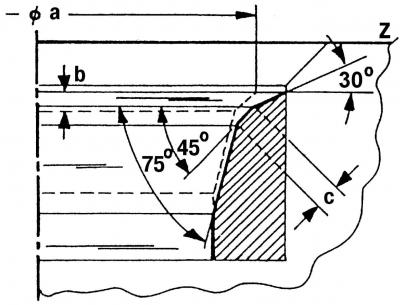
Pic. 40. Inlet valve seats: a - valve seat diameter (see table of adjustments and control); b - maximum size after repair; c - valve seat width, 1.7 mm; z - lower edge of the cylinder head; 30°- upper correction angle; 45°- angle of the chamfer of the valve seat; 75°- lower correction angle
- Check all valve seats for wear and scratches. On the working chamfers of saddles (valve contact area) there should be no pitting, corrosion or damage. Minor damage can be repaired by grinding the seats with a 45°cutter. At the same time, remove as little metal as possible. You can grind both manually and with a grinder. If the seats are badly worn, they should be remilled. The shape of the chamfers of the valve seats is shown in fig. 40 and 41;
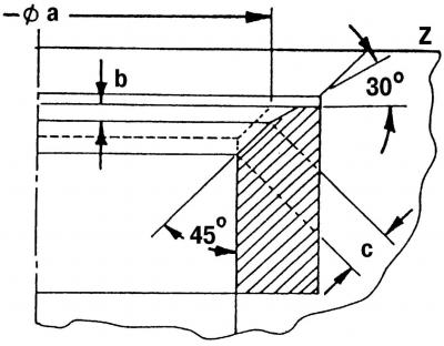
Pic. 41. Exhaust valve seats: a - valve seat diameter (see table of adjustments and control); b - maximum size after repair; c – valve seat width, 2.4 mm; z - lower edge of the cylinder head; 30°- upper correction angle; 45°- valve seat bevel angle
- take the following measurements to meet dimensions b, for this:
- insert the valve into its guide sleeve and press on the valve seat;
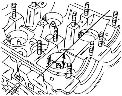
Pic. 42. Measuring the height of the protrusion of the end of the valve stem above the upper edge of the cylinder head
- measure the height of the protrusion of the end of the valve stem above the top edge of the cylinder head (pic. 42). To do this, place a measuring ruler on the plane of the cylinder head. On the intake valves, it should be 33.9 mm, and on the exhaust valves - 34.1 mm;
- calculate the value of b, for which it is necessary to subtract the minimum distance from the measured value.
This is necessary so as not to bore the valve seats in the cylinder head too much. The valve seats must also be milled if new guide bushings have been installed. For this you need:
- lightly machine the upper edge of the valve seat with a 45°cutter and then a 30°cutter to reduce the width of the valve seat to 1.7 mm for inlet and 2.0 mm for exhaust valves. Processing should be stopped as soon as the valve seat dimensions have reached the specified dimensions. The exhaust valve seats have diameter limiters. When processing, be careful not to damage these stops;
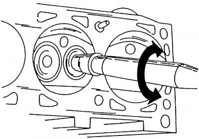
Pic. 43. Lapping the valve with a suction cup
- grind machined valve seats. To do this, apply a small amount of diamond lapping paste to the valve seat and install the valve in the appropriate seat. Attach a suction cup to the valve and rotate the valve with it back and forth (pic. 43);
- check the valve seat in place of the valve disc and O-ring. A continuous, frosted ring should be visible on both parts;
- draw a few lines with a pencil on the ring in the valve plate. Dashes should be drawn around the ring at intervals of approximately 1 mm. After that, carefully insert the valve into the guide sleeve, lower it onto the seat and turn it around 90°, applying a slight force to the valve;
- remove the valve and check if the pencil lines from the O-ring have disappeared;
- after lapping, thoroughly clean all parts of dirt and lapping paste. If the valve seat width corresponds to the specified dimensions, then the cylinder head can be installed. Otherwise, the valve seats must be reworked or, at the very least, a new cylinder head must be installed.
Valves
Remove carbon deposits from valves. Check if the rod is deformed and if there are cracks on the plate, for which:
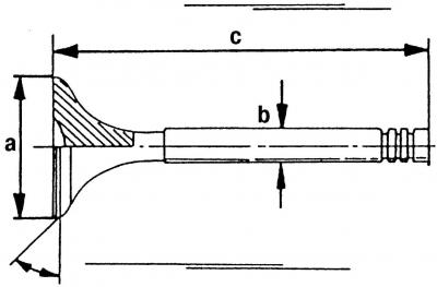
Pic. 44. Control dimensions of valves: a - valve disc diameter; b - valve stem diameter; c - valve length
- take measurements according to fig. 44 and replace any valves that do not meet these dimensions. The values a, b and c can be taken from the table of tolerances and control;
- if the end of the valve stem is worn, then it can be ground on a grinding machine, provided that no more than 0.50 mm of metal is removed during grinding;
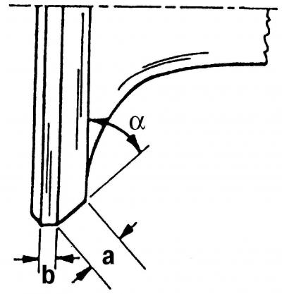
Pic. 45. Dimensions when grinding chamfers of valves: a = 45°; a = maximum 3.5 mm; b = minimum 0.5 mm
- intake valve discs can be ground on a valve grinder, provided that the value of b (pic. 45) will be less than 0.5 mm.
Attention! Grinding on the machine is not allowed for exhaust valves, as they are made of a special material. Only by lapping with paste can you try to bring the exhaust valves back to normal. Otherwise, they should be replaced.
Cylinder head
Wash the cylinder head thoroughly and clean the oil passages. Remove carbon deposits from the combustion chambers and from the surface of the exhaust channels with a wire brush. Thoroughly clean the contact surfaces of the cylinder head and cylinder block. Inspect the cylinder head. The bearings under the camshaft journals and in the holes for the valve lifters must not be scratched or damaged. Cracks in any places of the cylinder head are not allowed.
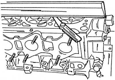
Pic. 46. Checking the cylinder head for deformation using a measuring ruler and a feeler gauge
Check the surface of the cylinder head for deformation (pic. 46).
To do this, place a measuring ruler on the head and use a feeler gauge to check the gap along, across and diagonally. If it does not exceed 0.10 mm, then the cylinder head can be ground. If the gap in any place is larger, then the cylinder head should be replaced, since the removal of a larger layer of metal can adversely affect engine compression.
Camshafts
Camshafts are not interchangeable primarily due to the presence of a Hall sensor on one of them. The shafts are identified by a spare part number.
When inspecting camshafts, pay attention to the surfaces of the bearing journals (bearing locations), cams, which must be well polished and not damaged. If signs of seizing or deep marks are found, the camshaft must be replaced.
Before installing the camshafts, the following work must be done:
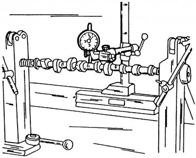
Pic. 47. Measuring the radial runout of the camshaft
- install the camshaft with the outer journals on two prisms or between the clamps of the lathe and install the measuring device in the place of the middle bearing (necks) camshaft (pic. 47);
- slowly rotate the camshaft and follow the readings of the measuring device. If, according to the readings of the device, the radial runout exceeds 0.01 mm, then the camshaft must be replaced, since it is deformed. Check the second shaft in the same way;
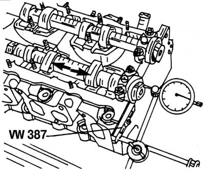
Pic. 48. Measuring the axial clearance of the camshaft
- to measure the axial clearance of the camshafts, insert both of them into the cylinder head (without pushers), secure with the end bearings and place the cylinder head on a flat surface. Install the measuring device from the end of the cylinder head and shake the shaft back and forth in the axial direction (pic. 48, shown by arrows). The axial clearance must not exceed 0.15 mm. Otherwise, the working surface of the bearing cover is worn out.

Visitor comments