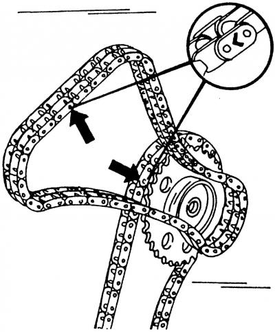
Pic. 92. Marking places for camshaft drive chains (shown by arrows)
If the cylinder head is not removed, the timing chains are marked (pic. 92) and none of the camshafts has been turned, sprockets and chains can be installed in this case.
If the cylinder head is removed, the timing gear must be fine-adjusted before the head is installed. In no case should the crankshaft be rotated if the chains are not put on the camshaft and crankshaft sprockets, as in this case the pistons will hit the valves. For this reason, the piston of the first cylinder should be set to the TDC position. Due to the fact that the engine has six cylinders, the piston of the first cylinder is only at TDC position every fourth revolution.
When describing the installation, we assume that all elements of the gas distribution mechanism drive are removed, as if the assembly is carried out after the complete disassembly of the engine. To install the timing gear drive, do the following:
- Turn the crankshaft of the engine so that the piston of the first cylinder is in the TDC position. To do this, on the removed engine, turn the crankshaft by rotating the flywheel, and on the installed engine and removed cylinder head, shift into gear and turn the front wheel hub. You can also temporarily screw on the vibration damper in order to turn the crankshaft. As already mentioned, it may take up to four revolutions before the piston of the first cylinder is in the TDC position;
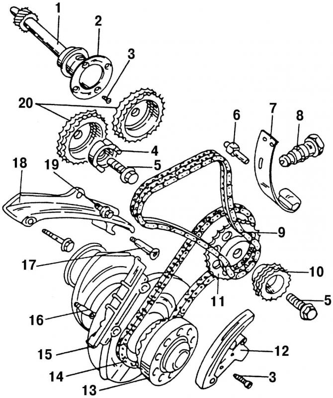
Pic. 91. Elements of the timing mechanism drive: 1 - intermediate shaft; 2 - driving ring; 3 - bolt, 10 Nm; 4 - sensor drive; 5 - bolt, 10 Nm; 6 - bolt, 25 Nm; 7 - elastic element of the tension device; 8 - tensioner of a double-row chain, 20 Nm; 9 - double row chain; 10 - double row chain drive sprocket; 11 - single-row chain drive sprocket; 12 - chain tensioner with shoe; 13 - chain drive sprocket built into the crankshaft; 14 - single-row chain; 15 - damper bar; 16 - special bolt, 25 Nm; 17 - pin with shoulder, 25 Nm; 18 - calmer; 19 - bolt, 20 Nm; 20 - crankshaft sprockets
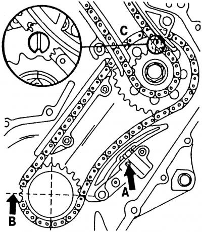
Pic. 94. Aligning the marks of both chains and sprockets: A - chain tensioner retainer; B - sprocket adjusting tooth; C - adjusting mark of the intermediate shaft sprocket
- put the lower single-row timing chain on the sprocket 13 (pic. 91) crankshaft. To do this, check that the adjusting tooth B (pic. 94) on the crankshaft sprocket is really located correctly. Tooth B is one of the teeth of the crankshaft sprocket, which is ground and should be in line with the joint of the No. 1 main bearing cap if the piston of the first cylinder is in the TDC position;
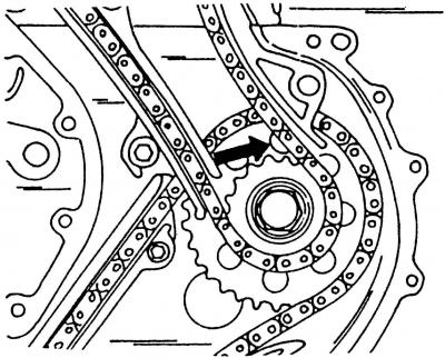
Pic. 95. Adjusting mark of the intermediate shaft sprocket
- install sprocket 11 (pic. 91) intermediate shaft single-row chain drive so that the adjustment mark C of the intermediate shaft sprocket is opposite the mark on the drive ring 2 (pic. 91). Put the lower single-row chain on the intermediate shaft sprocket (pic. 95);
- if an old chain is installed, then when installing it, the direction of movement marked earlier should be observed (pic. 92);
- put on a small star 10 (pic. 91) on the intermediate shaft, and, having fixed the intermediate shaft in a stationary state, tighten the bolt with a tightening torque of 100 Nm;
- install chain tensioner 12 (pic. 91) single row chain. Tighten their fastening bolts and fingers;
- check again that the adjustment mark C on the large intermediate shaft sprocket is opposite the mark on the guide ring;
- Install the cylinder head and rotate both camshafts so that the valve cams for the valves of the first cylinder are pointing round side down (those. positioned as they should be at TDC);
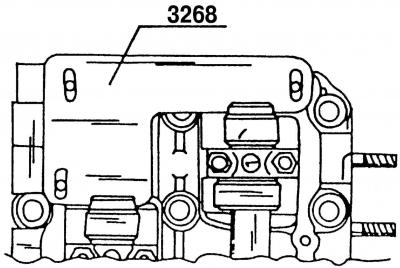
Pic. 96. Tool 3268 for camshaft alignment
- install tool 3268 on the cylinder head (pic. 96) to align the camshafts;
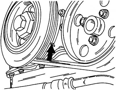
Pic. 97. Setting the piston of the first cylinder to the TDC position
- check that the piston of the first cylinder is in the TDC position (the groove on the belt drive pulley must match the mark) (pic. 97);
- put on both sprockets 20 (pic. 91) on the camshafts, and then put on the double row roller chain;
- if an old chain is installed, then when installing it, the direction of movement marked earlier should be observed (pic. 92);
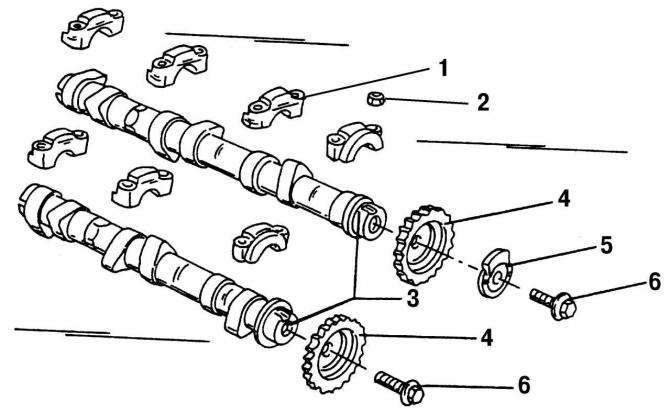
Pic. 31. Components of camshafts with bearing caps and sprockets: 1 - camshaft bearing cover; 2 - nut, 20 Nm; 3 - camshafts; 4 - camshaft sprockets; 5 - drive mechanism of the Hall sensor; 6 - bolts, 100 Nm
- on one of the camshafts, install the drive mechanism 5 (pic. 31) hall sensor;
- tighten both sprocket bolts on the camshafts;
- holding the camshafts stationary with an open end wrench «by 24 mm», put on the hexagon, tighten both sprocket mounting bolts with a tightening torque of 100 Nm. After tightening, check again that all adjustment marks are located correctly;
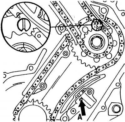
Pic. 98. Hydraulic chain tensioner: A - the place of weakening of the tensioner
- Install the chain tensioner. The piston located in the chain tensioner has a locking device that prevents the piston from moving back. Before installing the chain tensioner, insert a screwdriver into slot A (pic. 98) and turn the piston to unlock it. While doing this, squeeze the chain tensioner by hand. Install the tensioner on the chain and tighten the bolts with a tightening torque of 10 Nm;
- screw in the chain tensioner bolt 8 (pic. 91) into the cylinder head and tighten to 20 Nm. At the same time, he will tension the double-row roller chain with the prescribed force, that is, after that, no additional adjustment work on the chain tension is necessary;
- check again that the timing gear is installed and adjusted correctly and close the engine from the front.
All further work is carried out in the reverse order of disassembly.

Visitor comments