When disassembling, the location of all removable parts and parts should be marked in order to install them in their original position during assembly in case they are reused. This is especially important for pistons, valves, caps and bearing shells. Fold the parts in such a way that they are not mixed up.
Never mark bearings and seals by scratching their surface or using a punch. Only a rubber, plastic or leather-covered hammer may be used to remove any part of the engine.
Dismantle the engine in the following order:
- remove the parts located on the engine (ignition distributor, exhaust manifold, parts of the injection system, intake pipe with intake chamber, etc.);
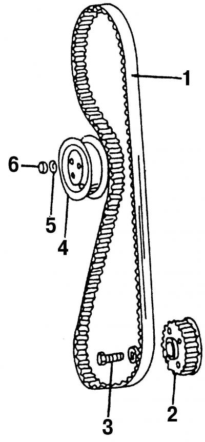
- remove the upper and lower parts of the protective cover of the timing mechanism drive and toothed belt 1 (see point 3.7.1);
- remove tensioner 4 toothed belt;

Pic. 103. Toothed drive belt with belt tensioner and crankshaft gear: 1 - toothed drive belt; 2 - a gear pulley of a cranked shaft; 3 - bolt, 80 Nm; 4 - tensioner gear drive belt; 5 - washer; 6 - nut, 45 Nm
- lock the crankshaft in a stationary state with a latch, unscrew the fastening bolt 3 and remove the toothed pulley 2 (pic. 103) from the crankshaft;
- remove the cooling system pump;
- remove the oil filter and oil cooler (see subsection 4.5);
- remove the oil dipstick along with the guide;
- unscrew the bolts and remove the cylinder head cover and discard the gasket immediately;
- remove the cylinder head;
- turn the engine over with the crankcase up and remove the pan with the gasket;
- unscrew the oil pump mounting bolts from the bottom of the crankcase and remove it;
- number (preferably in color) connecting rod bearing caps. Their numbers must match the numbers of the cylinders;

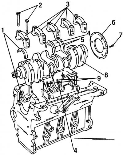
Pic. 104. Disassembled cylinder block: 1 - bearing shell No. 1, 2, 4 and 5; 2 - cover bolts; 3 - bearing caps; 4 - bearing shell No. 3; 5 - thrust semi-ring on the bearing cover; 6 - gear rim of the crankshaft speed sensor; 7 - bolt, 10 Nm (turn another 90°); 8 - crankshaft; 9 - thrust half rings of the cylinder block
- unscrew bolts 2 one by one (pic. 104) securing the bearing caps, with the two connecting rod bearings always in the BDC position when their caps are removed;
- remove the connecting rods one by one with the pistons from the cylinder bores. The bearing shells and caps must be screwed onto the respective connecting rods immediately. Connecting rod bearings are screwed «malleable screws» and their reuse is unacceptable;
- number the main bearing caps with numbers, bearing #1 on the pulley side and #5 on the flywheel side (see section 2.6.1) and remove the crankshaft;
- remove the intermediate shaft pulley;
- unscrew the mounting bolts and remove the intermediate shaft holder. Remove the intermediate shaft from the engine.
If, after disassembling the engine, metal chips or other signs of metal damage are found inside the cylinder block, then you need to thoroughly clean the oil channels and oil injection nozzles, and also replace the oil recirculation check valve and oil cooler, as metal particles will certainly be there.
The crankcase assembly scheme is shown in fig. 104. Front and rear oil seal holders and intermediate shaft are not shown here, as they will be described in clause 3.6.4 and subsection 3.9).

Visitor comments