- check the connections of the electrical wires and connectors of the high voltage transformer, the ignition output stage, the computer and the ignition distributor (2.0 liter engine). These connections may be oxidized or loosen somewhat due to vibration;
- check the integrity of all electrical wires;
- check the reliability of the fit of the HV wires and the condition of their insulating coating. Wiped insulation of HV wires leads to electrical losses and breakdown of a spark discharge;
- check the condition of the distributor cap on the 2.0 liter engine. It should not have cracks and signs of burning, otherwise sparks may form inside the distributor cap.
Checking the voltage supply to the high voltage transformer
Check using a voltmeter in the following order:
- check the corresponding fuse No. 15;
On a 2.0 liter engine:

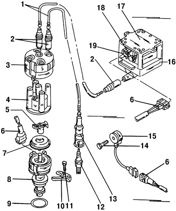
Pic. 210. Elements of the ignition system on a 2.0-liter engine (with Simos injection system): 1 - wire VN, to the spark plug; 2 - plug suppressing radio interference; 3 - protective cover; 4 - ignition distributor cover; 5 - slider of the ignition distributor; 6 - three-pin plug; 7 - dust cover; 8 - ignition distributor with Hall sensor; 9 - O-ring; 10 - clamping rail; 11 - bolt, 25 Nm; 12 - spark plug, 30 Nm; 13 - tip of the VN wire, to the spark plug; 14 - bolt, 20 Nm; 15 - knock sensor (G61); 16 - high voltage transformer (N 152); 17 - output stage of the high voltage transformer (N157); 18 - terminal «15»; 19 - terminal «1»
- disconnect the three-pin connector 6 (pic. 210) from a high voltage transformer;

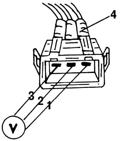
Pic. 213. View of the plug block of the high voltage transformer (2.0 liter engine). Numbers indicate terminals
- connect to both external pins of the plug-in socket - pin «1» (positive) and contact «3» («weight») - voltmeter (pic. 213);
- turn on the ignition. The voltmeter should show a voltage close to the battery voltage. If this is not the case, then check all electrical wire connections, up to the ignition switch;
On VR6 engine:

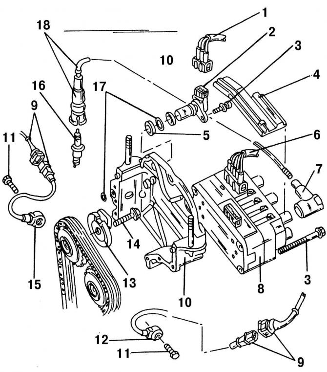
Pic. 211. Elements of the ignition system on the VR6 engine (with Motronic injection system): 1 - three-pin plug-in block (black color), for the Hall sensor; 2 - Hall sensor; 3 - bolt, 10 Nm; 4 - HV wire guide, to the high voltage transformer; 5 - spacer ring; 6 - five-pin plug, to the high voltage transformer; 7 - plug suppressing radio interference; 8 - high voltage transformer; 9 - plug block of the knock sensor; 10 - cover of the camshaft drive mechanism; 11 - bolt, 20 Nm; 12 - knock sensor II, on the suction side; 13 - Hall sensor disk; 14 - bolt, 100 Nm; 15 - knock sensor l, on the exhaust side; 16 - spark plug, 25 Nm; 17 - O-ring; 18 - spark plug tip
- disconnect the five-pin connector 6 (pic. 211) from a high voltage transformer;

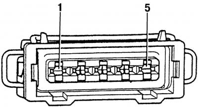
Pic. 214. View of the high voltage transformer plug on the VR6 motor. Measure between terminals «1» and «5»
- connect a voltmeter to the terminals «1» and «5» (pic. 214);
- turn on the ignition. The voltmeter should show a voltage close to the battery voltage. If this is not the case, then check all electrical wire connections, up to the ignition switch. In addition, the connection between the terminal may be broken «5» and «weight».
Secondary voltage test (high voltage part) ignition systems
Although the above checks may give a positive result, this does not mean that a spark is being generated in the engine. To check, you need a simple spark gap with two pairs of metal rods (electrodes), fixed on a plate of insulating material (plastic, textolite). The lower part of the rods, together with the insulators, must correspond in shape and size to the dimensions of the insulator and the tip of the spark plugs. Screws with pointed ends are wrapped in the upper part of the rods. The gap between the ends of the screws can be adjusted by turning the screws.
Care must be taken when checking the high voltage part. For this purpose, the arrester must be covered from above with a cover made of insulating material with viewing windows. Mount the arrester on the car body. Check the high-voltage part of the ignition system in the following order.
2.0 liter engine:
- disconnect the HV wires from the spark plugs;
- attach the wire ends to the arrester electrodes;
- connect the wires from candles No. 1 and No. 4 to one pair of spark gap electrodes, and from candles No. 2 and No. 3 - to another pair of electrodes;
- set the gap between the electrodes 7-10 mm and crank the engine with a starter;
- should be sequential «overshoot» sparks between pairs of electrodes 2 and 5;
- if sparking on the arrester is normal, then it is necessary to check the spark plugs;
- if there is no sparking on one pair of electrodes, then the electrical circuit must be checked; HV wires, ignition coil and connection of the ignition coil to the output stage of the high voltage transformer;
- if the ignition distributor was removed, there is sparking, the candles are in good order, and the engine does not start, check the correct installation of the ignition distributor.
VR6 engine
The check is carried out in the same way as it was described for the 2.0-liter engine, but you should disconnect the lugs of the HV wires from spark plugs No. 1 and No. 6 and connect them as described. This allows both ignition coils to be tested. At your discretion, also unscrew and check the HV wires from spark plugs No. 3 and No. 4, as well as No. 2 and No. 5.
To check, you can use the simplest arrester not with two pairs of metal rods (electrodes), fixed on a plate of electrically insulating material, but with three pairs, which will allow you to check all the HV wires of the VR6 engine at once.
If during the described test everything works fine, then you should look for the problem further. Otherwise, you should drive the car to the service station.

Visitor comments