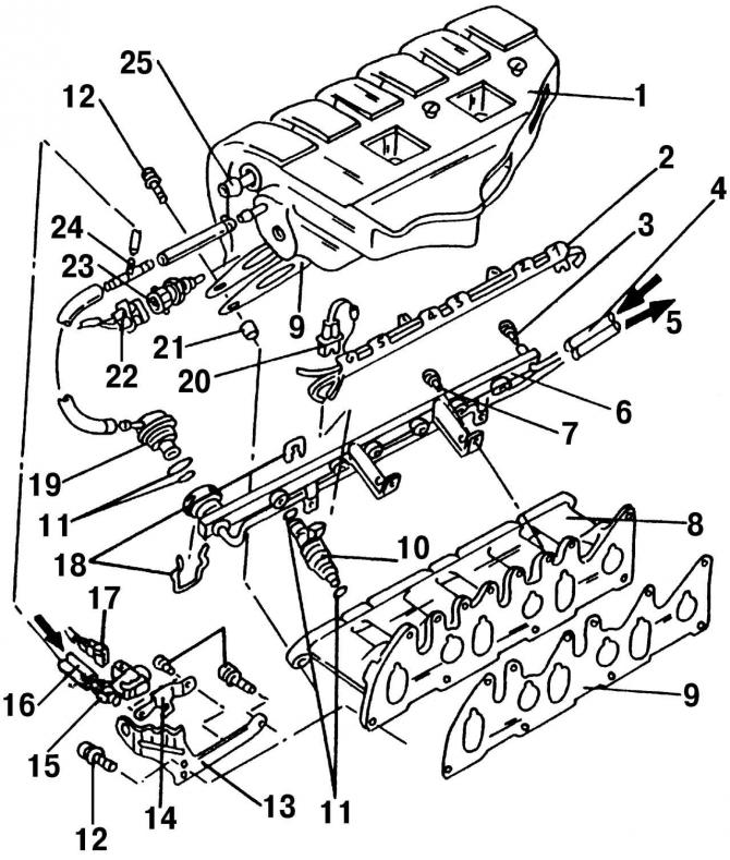
Pic. 201. The top and bottom parts of an inlet collector and the details located nearby: 1 - the upper part of the intake manifold; 2 - HV wire guide; 3 - sealing ring; 4 - fuel supply hose; 5 - fuel return hose; 6 - fuel distribution line; 7 - bolt, 10 Nm; 8 - the lower part of the intake manifold; 9 - gasket, replace; 10 - nozzle; 11 - O-ring; 12 - bolt, 25 Nm; 13 - lifting eye; 14 - secondary air supply valve bracket; 15 - secondary air supply valve; 16 - vacuum hose; 17 - plug, blue; 18 - clamps; 19 - fuel pressure regulator; 20 - plug, black; 21 - guide sleeve; 22 - plug, black; 23 - temperature sensor; 24 - T-shaped fitting; 25 - vacuum hose, to the brake booster
Fuel pressure regulator 19 (pic. 201) is a diaphragm bypass valve and is installed at the end of the fuel distribution line 6. Fuel pressure acts on the regulator diaphragm on one side, and on the other hand, the pressure of the regulator spring and pressure (or vacuum) in the intake pipe. The function of the regulator is to maintain a constant differential pressure across the nozzle 10.
The fuel pressure regulator is connected via a hose to the throttle body and reacts to a decrease in pressure in the intake pipe. When the pressure in the intake pipe decreases (less throttle opening) the regulator reduces the fuel supply pressure. At the same time, the regulator valve opens and excess fuel is drained back into the fuel tank through the drain line. As the crankshaft speed increases, the pressure in the intake pipe increases and the regulator increases the fuel supply pressure.

Visitor comments