The VR6 engine ECU has a built-in fault memory that detects malfunctions in the operation of the ECU and Motronic elements and enters them into the ECU memory. In the event of a malfunction of the coolant temperature sensors, intake air temperature, air flow meter potentiometer, the computer starts to work according to the values taken «default». After the computer returns to normal mode, the use of the values taken «default», stops.
To facilitate troubleshooting, it is possible to request current parameters by means of the ECU and actuate one or another element of the system.
To search for faults entered into the memory device of the computer, it is necessary to use the diagnostic stands of the company that produced the car. After faults are repaired in the workshop, they are erased from the fault recorder, allowing the fault recorder to record new faults as they are detected, without confusing them with old faults.
Idle speed and CO share are electronically controlled and cannot be checked and adjusted without using the fault memory. Idle speed can be measured using a tachometer specially designed for this engine and should be between 660 and 740 min-1. If they do not correspond to the norm, then you should contact the service station.
To correctly measure the number of idle revolutions, follow these recommendations:
- warm up the engine to operating temperature. It must be at least 80°C;
- turn off all electrical consumers;
- turn off the air conditioner, if any;
- the exhaust system must be in good condition;
- measure the proportion of CO using a special device. The connection point for the CO meter is located next to the throttle body and is integrated into the downpipe. The permissible share of CO is from 0.3 to 1.2%.

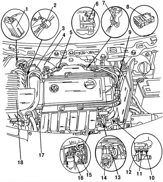
Pic. 198. Location of elements of the Motronic injection system in the engine compartment of the VR6 engine: 1 - a vessel with activated carbon; 2 - solenoid valve (N80); 3 - mass air flow sensor (G70); 4 - inlet hose; 5 - throttle body; 6 - knock sensor No. 1 (G61); 7 - connection with «weight»; 8 - electronic control unit (ECU) injection and ignition system «Motronic»; 9 - ignition coil (N152); 10 - temperature switch; 11 - temperature sensor (G62); 12 - temperature switch; 13 - temperature sensor (G72); 14 - fuel pressure regulator; 15 - engine crankshaft speed sensor (G28); 16 - knock sensor No. 2 (G66); 17 - nozzles (N30, N33, N83, N84); 18 - air filter. (The designations in brackets correspond to the designations on the electrical diagrams)
Location of elements of the electronic engine control system (ECM) VR6 Motronic shown in (pic. 198).
The ECM consists of the following main elements:
- activated carbon tank 1 (pic. 198) located in the right wheel arch;
- solenoid valve 2 opens and closes the connection between the activated carbon tank and the engine;
- mass air flow sensor 3 is located in the flow of air sucked through the air filter between the air air filter and the intake hose;
- inlet hose 4 has a connection for crankcase ventilation heating;
- preheating of the control part of the throttle valve is carried out using a coolant;
- functions of knock sensors 6 and 16 are described in section 8;
- The engine ECU is located behind the instrument panel in the passenger compartment;
- the functions of the ignition coil 9 are described in section 8);
- temperature switches close or open depending on the temperature of the coolant. Temperature switch 10 is used to turn off the air conditioner, as well as the third stage of the cooling fan. It has a brown plug and a four-pin connector. Only available on vehicles with air conditioning installed;
- temperature sensor 11 has a blue plug and a two-pin connector. It informs the ECU about the coolant temperature;
- temperature sensor 13 informs the computer about the air temperature in the intake pipe;
- engine speed sensor 15 provides information to the ECU about the current engine speed.

Visitor comments