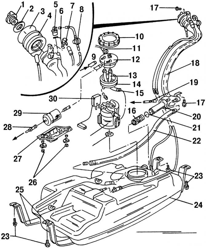
Pic. 206. Details of the power supply system located near the fuel tank: 1 - fuel tank cap; 2 - sealing ring; 3 - safety ring; 4 - rubber seal; 5 - check valve; 6 - O-shaped sealing ring; 7 - ventilation valve; 8 - pressure reducing valve; 9 - return pipeline; 10 - union nut; 11 - plug, black, pump and fuel quantity sensor; 12 - flange; 13 - supply fuel hose; 14 - sealing ring; 15 - return hose; 16 - check valve; 17 - bolt, 10 Nm; 18 - filler pipe; 19 - ventilation pipeline; 20 - sealing ring; 21 - safety ring; 22 - ventilation pipeline; 23 - bolts, 25 Nm; 24 - fuel tank; 25 - fastening of the fuel tank; 26 - bolts, 20 Nm; 27 - fuel filter cover/holder; 28 - fuel line (black color); 29 - fuel filter (observe the direction of fuel flow); 30 - fuel level sensor in the tank; 31 - fuel pump; 32 - strainer
The fuel filter is designed to trap particulates that can cause the fuel system to malfunction. It is installed under a metal cover 27 (pic. 206) next to the fuel tank 24. The filter is built into the supply line between the fuel pump and the fuel distribution line. The filter has an arrow that indicates the direction of fuel flow. When installing a new filter, you should pay attention to this. The filter has a long service life, so it does not require replacement during technical inspections and car maintenance. It should only be changed if it is clogged.

Visitor comments