Removing
Instructions: Please note that when performing further work that requires loosening the hex bolt with a dodecagonal head, a partial loosening of the tightening must be performed on a stationary vehicle on wheels.
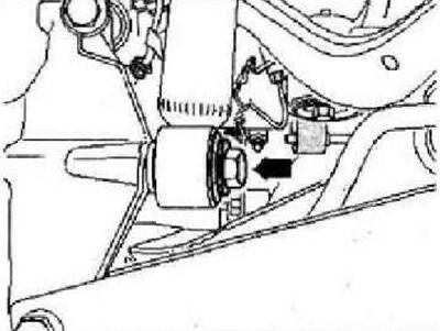
Remove wheels. Remove coil springs. Remove the rear muffler of the exhaust system. Disconnect the electrical connectors located between the rear axle assemblies and the body. Remove bolt -arrow-.
Remove retaining clip -1-.
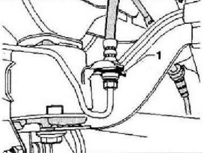
Instruction: Do not disconnect the brake pipe.
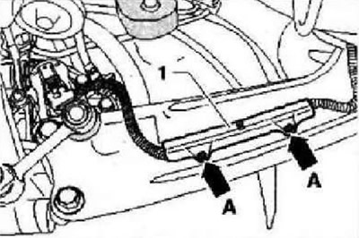
Disconnect the electromechanical parking brake electrical connectors at the brake caliper. Remove fastener -1- by pressing out pins of spacer clips -arrows A-.
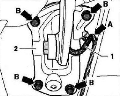
Detach cable -1- from support bracket -arrow A-. Mark position of support bracket -2- on body. Remove bolts -arrows B-. Unplug connector at rear left vehicle level sender -G76-.
Check if there is a label (colored labels) rear axle drive shaft and rear final drive flange -arrows-. If there is no marking, mark the relative position of the flexible coupling and final drive flange -arrows-. Unplug connectors for rear right speed sender -G44- and rear left speed sender -G46-.
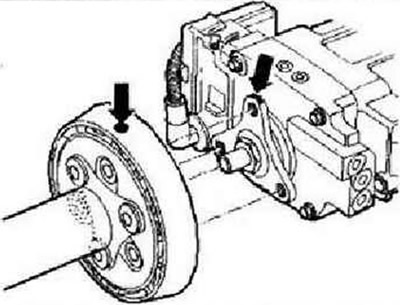
Remove bolts securing flexible coupling and balancing weight for rear axle shaft rear tube from final drive flange -arrows-.
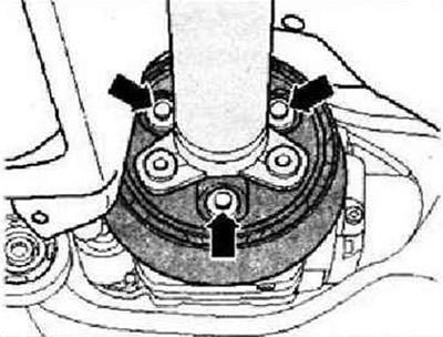
Loosen central support bolts -arrows- two turns.
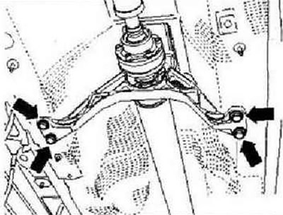
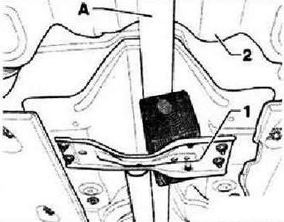
Support the rear axle drive shaft -A- in the area of the tunnel cross member -1- with a block of wood. Move rear axle shaft rear tube as far as possible towards gearbox. Disconnect the Haldex clutch connector located at the top of the final drive.
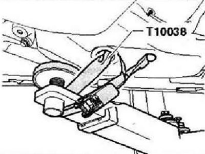
Secure vehicle to lift arms on both sides with straps -T10038-.
WARNING: Otherwise, it may slide off the lift!
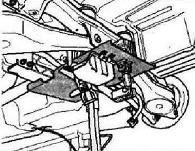
Position engine and gearbox jack -VAG 1383 A- with universal gearbox support -VAG 1359/2- under subframe and secure subframe with belt.
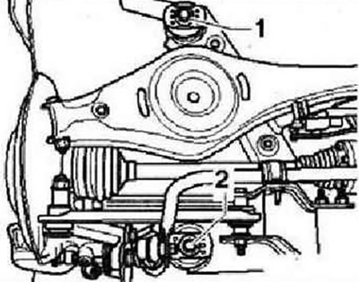
To lock the position of the subframe at points -1- and -2- on both sides of the vehicle, screw in locking pins -T10096- one by one. Unscrew bolts -1- or -2- on both sides.
Instructions: For clarity, the figure shows only the left side of the vehicle.
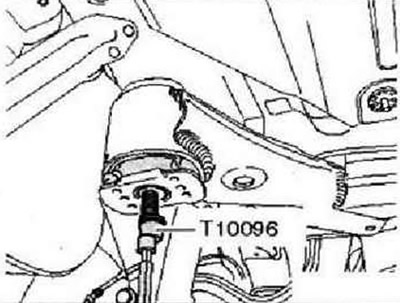
Lock subframe in position with pins -T10096-.
Note: Locking pins -T10096- must be tightened to a maximum torque of 20 Nm, otherwise the threads may be damaged.
On both sides, replace bolts for subframe in turn with retainers -T10096- and tighten to 20 Nm. The position of the subframe is now fixed. Carefully lower the complete subframe with the units installed on it by about 2 cm.
Detach brake lines on both sides -arrow-.
Instruction: In this case, the fastening clips are destroyed, they must be replaced.
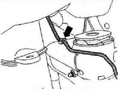
Detach brake lines from mountings -arrows- above drive shaft flanges -1-.
Instruction: In this case, the fastening clips are destroyed, they must be replaced.
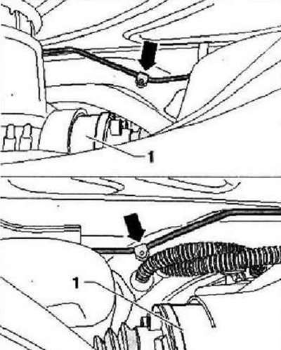
Carefully lower the subframe assembly with the units installed on it.
Instruction: When lowering, avoid getting caught in the brake hoses, electrical cables and centering pin on the final drive flange.
Installation
Installation is carried out in the reverse order.
Instructions: Replace broken brake line clips on the subframe.
When installing the cable for the electromechanical parking brake, strictly observe dimension -a- between connector -1- and holder -2-.
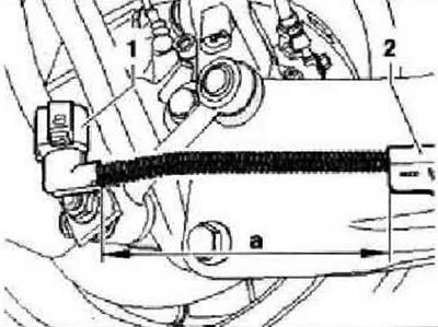
Dimension -a- = 150 mm.
Tightening torques
| Subframe to the body. Use only new bolts | 90 Nm and tighten by 90° |
| Shock absorber to wheel bearing housing | 180 Nm |
| Support bracket for body. Use only new bolts | 50 Nm and tighten by 45° |

Visitor comments