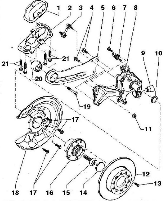
- 1 - Lid
- 2 - Support bracket
- 3 - Stabilizer link, connects stabilizer to trailing arm/wheel bearing housing
- 4 - Bolt, tighten in the correct sequence, M12x1.5x40, 90 Nm and tighten by 45°, replace after each removal
- 5 - Trailing arm
- 6 - Bolt, M6x16, 8 Nm
- 7 - Rear right speed sender -G44- / rear left speed sender -G46-, can be checked in guided fault finding with tester -VAS 5051-, before installing speed sender clean hole and apply some grease -G 000 650-
- 8 - Wheel bearing housing
- 9 - Silent block
- 10 - Washer, washer chamfer facing outwards
- 11 - Nut, 40 Nm, replace after each removal
- 12 - Brake disc
- 13 - Bolt, 4 Nm
- 14 - Protective cap, replace after each removal. Proper sealing is only possible by fitting a new protective cap
- 15 - Bolt, loosening and tightening with socket wrench X2N 18 -T10162-, M16x1.5x70, 200 Nm and tighten by 180°, replace after each removal
- 16 - Wheel hub with bearing (bearing unit), the magnetic ring for the operation of the ABS sensor is built into the wheel hub. The wheel hub and bearing are assembled in a common housing (bearing unit). The bearing assembly does not require adjustment and maintenance. Adjustments and repairs are not possible!
- 17 - Bolt, M6x10, 12 Nm
- 18 - Shield
- 19 - Bolt, M12x1.5x80, 90 Nm and tighten by 90°, replace after each removal
- 20 - Silent block
- 21 - Bolt, M10x35, 50 Nm and tighten by 45°, replace after each removal

Visitor comments