Removing
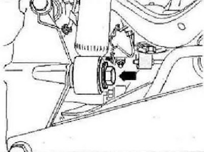
Remove wheels. Remove coil springs. Disconnect the electrical connectors located between the rear axle assemblies and the body. Remove bolt -arrow-.
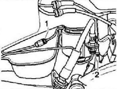
Disconnect brake lines at points -1- and -2-. Disconnect the electrical connectors for the electromechanical parking brake on the brake caliper.
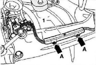
Remove fastener -1- by pressing out pins of spacer clips -arrows A-.
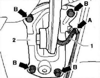
Detach cable -1- from support bracket -arrow A-. Mark position of support bracket -2- on body. Remove bolts -arrows B-. Unplug connector at rear left vehicle level sender -G76-.
Secure vehicle to lift arms on both sides with straps -T10038-.
WARNING: Otherwise, it may slide off the lift!
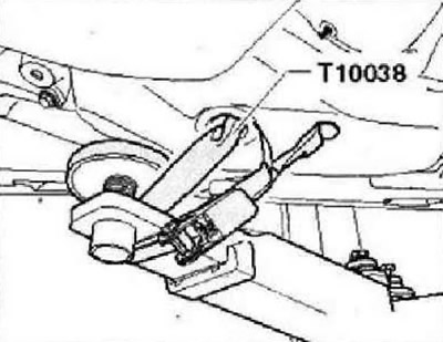
Position engine and gearbox jack -VAG 1383 A- with universal gearbox support -VAG 1359/2- under subframe and secure subframe with belt.
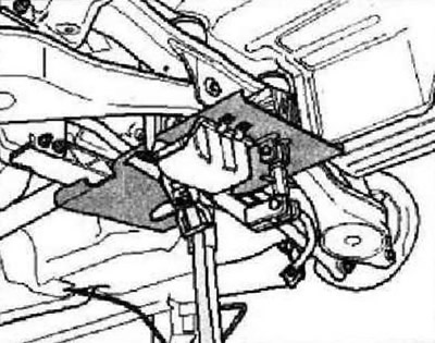
Unscrew bolts -1- or -2- on both sides.
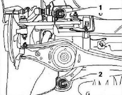
Instructions: For clarity, the figure shows only the left side of the vehicle. To fix the position of the subframe at points -1- and -2- on both sides of the vehicle, the locking pins -T10096- must be screwed in successively.
Lock subframe in position with pins -T10096-.
Note: The locking pins -T10096- must be tightened to a maximum torque of 20 Nm, otherwise the thread may be damaged.
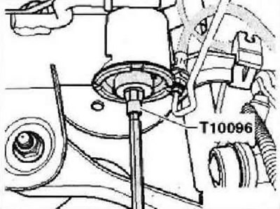
On both sides, replace bolts for subframe in turn with retainers -T10096- and tighten to 20 Nm. The position of the subframe is now fixed. Carefully lower the subframe assembly with the units installed on it.
Instructions: When lowering, avoid catching brake hoses and electrical cables.
Installation
Installation is carried out in the reverse order. When installing the cable for the electromechanical parking brake, strictly observe dimension -a- between connector -1- and holder -2-.
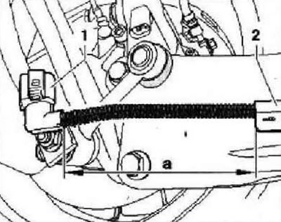
Dimension -a- = 150 mm. Bleed the brake system.
Tightening torques
| Subframe to the body. Use only new bolts | 90 Nm and tighten by 90° |
| Shock absorber to wheel bearing housing | 180 Nm |
| Support bracket for body. Use only new bolts | 50 Nm and tighten by 45° |

Visitor comments