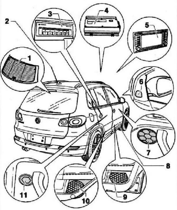
- 1 - Radio antenna built into the rear window
- 2 - Antenna phone / navigation system (GPS) -R66-, located at the rear of the roof
- 3 - CD changer -R41 - for 6 CDs, installed under the folding center armrest
- 4 - Audio amplifier -J525-. under front left seat
- 5 - Control unit with radio navigation display -J503- (RNS 2 with MFD)
- 6 - Front right tweeter -R22- and front left tweeter -R20- are located in the triangular trim of the mirror base on the front right and left doors
- 7 - Front right midrange loudspeaker -R104- and front left midrange loudspeaker -R103 are located in the front left and right door trims
- 8 - Aerial selection control unit -J515-, under front right seat
- 9 - Front right bass loudspeaker -R23- and front left bass loudspeaker -R21- are located in the front left and right door trims
- 10 - Rear right bass loudspeaker -R17- and rear left bass loudspeaker -R15- are located in the left and right rear door trims
- 11 - Rear right tweeter -R16- and rear left tweeter -R14- are located in the left and right rear door trims
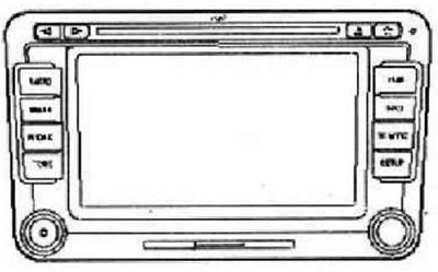
The RNS 510 radio navigation system combines the functions of a navigation system with a high-quality RDS radio. Its main functions are as follows: RDS radio, 6.5" color LCD display, navigation system with GPS receiver, integrated antenna diversity system, integrated DAB digital radio tuner, DVD drive for navigation system, video and audio playback, SD card reader, traffic announcement memory (Traffic Information Memory, TIM), Korridor function, MP3 and WMA file playback. The RNS 510 radio navigation system has four speaker outputs. On request, two full-range loudspeakers can be installed in the rear of the cabin. The capabilities of the RNS 510 radio navigation system can be extended by adding the following components: CD changer, multifunction steering wheel, TV tuner, amplifier, universal mobile phone kit (UHV Low), universal mobile phone connection set Premium (VAR), rear-seat infotainment center (RSE), The rooftop navigation system is equipped with an appropriate antenna.
Connectors for radio navigation system RNS 510
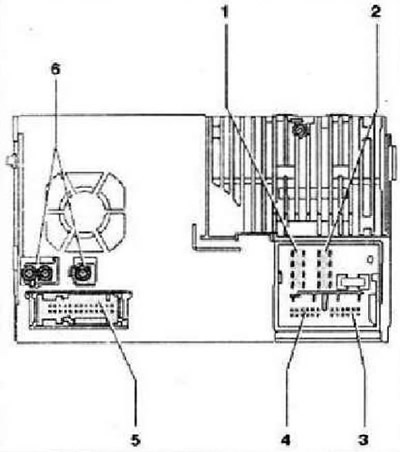
- 1 - Connector 1, 8-pin
- 2 - Connector 2, 8-pin
- 3 - Connector 3, 12-pin
- 4 - Connector 4, 12-pin
- 5 - Connector 5, 26-pin
- 6 - Connectors 6 for connecting antennas
Connector 1, 8-pin, speaker output
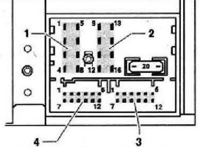
- 1 - Rear right speaker, plus
- 2 - Front right speaker, plus
- 3 - Front left speaker, plus
- 4 - Rear left speaker, plus
- 5 - Rear right speaker, minus
- 6 - Front right speaker, minus
- 7 - Front left speaker, minus
- 8 - Rear left speaker, minus
Instructions: If there is an external amplifier, these outputs are used as a line input for the amplifier. The receiver in this case is programmed under production conditions for a 12 dB line output mode instead of a 26 dB power output.
Connector 2.8-pin, power supply, CAN bus
- 9 - CAN high bus
- 10 - CAN low bus
- 11 - Power supply for the display, plus, only as an option for the radio module in the Low version
- 12 - Power supply, negative, terminal 31
- 13 - Display HS CAN-Bus low, only as an option for radio module in Low version, not for Midline version
- 14 - Display HS CAN-Bus high, only as an option for radio module in Low version, not for Midline version
- 15 - Power supply, positive, terminal 30
- 16 - Anti-theft control signal, SAFE, plus
Connector 3, 12-pin, phone and microphone signals
- 1 - Microphone input, minus
- 2 - AUX output, audio, right channel
- 3 - AUX output, total ground
- 4 - Microphone output, minus
- 5 - Incoming phone audio signal, left channel, minus
- 6 - Phone audio input, right channel, minus
- 7 - Microphone input, plus
- 8 - AUX output, audio, left channel
- 9 - Microphone output, plus
- 10 - Muting the sound when talking on the phone
- 11 - Incoming phone audio signal, left channel, plus
- 12 - Incoming phone audio signal, right channel, plus
Connector 4, 12-pin, CD changer control, audio CD signal input
- 1 - AUX signal input, left channel
- 2 - Ground AUX
- 3 - CD changer, audio ground
- 4 - CD changer, power supply, positive, terminal 30, continuous load 1 A, short-term peak load 5 A
- 5 - Not used
- 6 - CD changer, DATA OUT (data exchange for CD changer control, from radio navigation system to CD changer)
- 7 - AUX signal input, right channel
- 8 - CD changer, left channel, CD/L
- 9 - CD changer, right channel, CD/R
- 10 - CD changer, control wire, switched plus
- 11 - CD changer, DATA IN (data exchange for CD changer control, from CD changer to radio navigation system)
- 12 - CD changer, CLOCK (internal verification protocol for data flow control)
Connector 5, 26-pin, audio and video
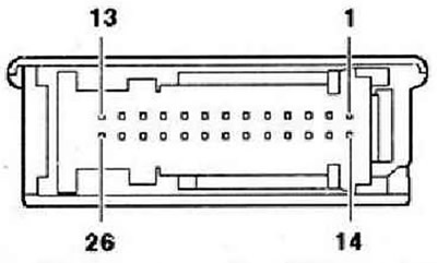
- 1 - Reserved for Debug RX protocol
- 2 - Reserved for Debug TX protocol
- 3 - Not used
- 4 - Video signal input, RGBS, minus
- 5 - Not used
- 6 - Built-in universal mobile phone connection kit, mobile phone recognition
- 7 - Built-in universal kit for mobile phone connection, cradle and key recognition
- 8 - Built-in universal kit for connecting a mobile phone, cradle, antenna diagnostics
- 9 - Video signal input, RGBS, minus
- 10 - Video signal input NF, right
- 11 - Video input, screen ground
- 12 - Video signal input, vertical and horizontal synchronization
- 13 - Video signal input, green
- 14 - Not used
- 15 - Not used
- 16 - Not used
- 17 - Not used
- 18 - Not used
- 19 - Built-in universal kit for connecting a mobile phone, cradle, minus
- 20 - Built-in universal kit for connecting a mobile phone, switched terminal 30
- 21 - Not used
- 22 - Video signal input NF, minus
- 23 - Video signal input NF, left
- 24 - Video signal input, RGBS, minus
- 25 - Video signal input, blue
- 26 - Video input, red
Connectors 6 for connecting antennas
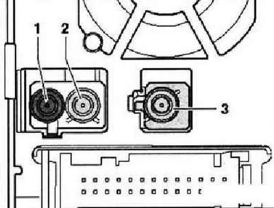
- 1 - Radio antenna connector, AM and FM2 bands, double FAKRA connector, uncoded, 50 ohm impedance, cream white
- 2 - Radio antenna connector, FM1 band, double FAKRA connector, B-coded, impedance 50 Ohm, cream white
- 3 - Navigation system antenna connector, FAKRA, coding C, impedance 50 Ohm, color blue
Electronic anti-theft system
The radio navigation system RNS 510 has a convenient electronic anti-theft system that works in conjunction with the instrument cluster. When connecting the radio navigation system after a power failure, it works without entering the security code. Prerequisites: the first activation of the electronic anti-theft protection system has been carried out, the radio navigation system is installed in the same vehicle. Re-commissioning of a previously blocked radio navigation system is only possible after entering the correct code for the electronic anti-theft system. Use tester -VAS 5051- or tester -VAS 5052- or later versions to determine the security code. Number cards and stickers are no longer used.
Note: To determine the security code, use tester -VAS 5051- or tester -VAS 5052- or later. The toaster must have an online connection and the user must have the appropriate rights to request the code.

Visitor comments