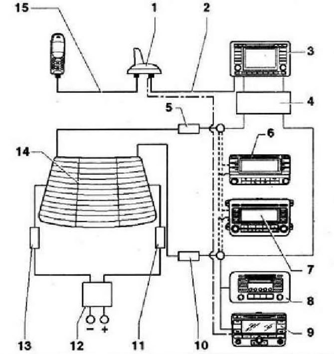
- 1 - Antenna -R11- for operation of navigation system, telephone and auxiliary heater remote control, located at the rear of the roof
- 2 - Antenna cable for signal transmission to the navigation system
- 3 - Control unit with display for radio navigation system -J503-, designation RNS 510 radio navigation system with DVD drive, with two antenna cables for radio reception, antenna diversity function, with one antenna cable for signal transmission to the navigation system (roof antenna cable)
- 4 - Aerial selection control unit -J515-, only installed in conjunction with radio and navigation display control unit -J503- RNS MFD 2 with CD drive
- 5 - Aerial amplifier -R24-, FM signal
- 6 - Radio -R-, RCD 300, two aerial cables for AM/FM, antenna diversity function integrated in the radio
- 7 - Radio -R-, RCD 500, two aerial cables for AM/FM, antenna diversity function integrated in the radio
- 8 - Control unit with display for radio navigation system -J503-, radio navigation system RNS 300, with single antenna cable for FM/AM radio reception, no antenna separation function, with one antenna cable for signal transmission to the navigation system (roof antenna cable)
- 9 - Aerial amplifier 2 -R111-, FM and AM signals
- 10 - Frequency filter for frequency modulation (FM) in the positive wire -R179-, in the wiring harness, its function is to prevent the transmission of the antenna signal to ground
- 11 - Frequency filter for amplitude modulation (AM) -R177-, in the tailgate in the middle, its function is to prevent the transmission of the antenna signal to ground
- 12 - Frequency filter for frequency modulation (FM) in the negative wire -R178- in the wiring harness, its function is to prevent the transmission of the antenna signal to ground
- 13 - Rear window with two antenna connectors for receiving radio signals in the FM and AM bands
- 14 - Telephony antenna cable
Components of aerial system for vehicles with radio without telephone/auxiliary heater remote control
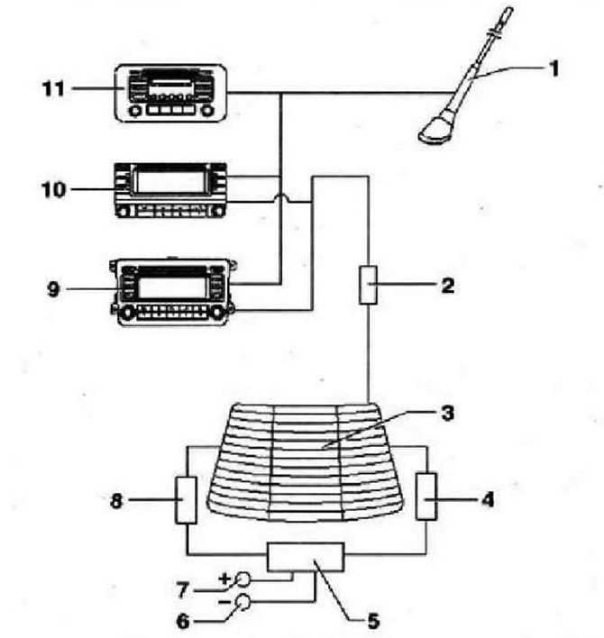
- 1 - Antenna -R11-. Roof whip antenna for FM/AM radio reception, located at the rear of the roof
- 2 - Aerial amplifier 2 -R111-
- 3 - Rear window with one antenna connector, only for receiving a signal in the FM band
- 4 - Frequency filter for frequency modulation (FM) in the positive wire -R179-, in the wiring harness, its function is to prevent the transmission of the antenna signal to ground
- 5 - Place of connection of the frequency filter, because the antenna in the rear window is not designed to receive an AM signal, and a frequency filter for amplitude modulation is not needed either (AM). Therefore, only the power supply wires for the heated rear window are connected in this place
- 6 - Power supply of the rear window heating element, minus
- 7 - Power supply for the rear window heating element, plus
- 8 - Frequency filter for frequency modulation (FM) in the negative wire -R178- in the wiring harness, its function is to prevent the transmission of the antenna signal to ground
- 9 - Radio -R-, RCD 500, two aerial cables for AM/FM, antenna diversity function integrated in the radio
- 10 - Radio -R-, RCD 300, two aerial cables for AM/FM, antenna diversity function integrated in the radio
Components of an antenna system for vehicles with radio/radio navigation systems (with telephone/auxiliary heater remote control)
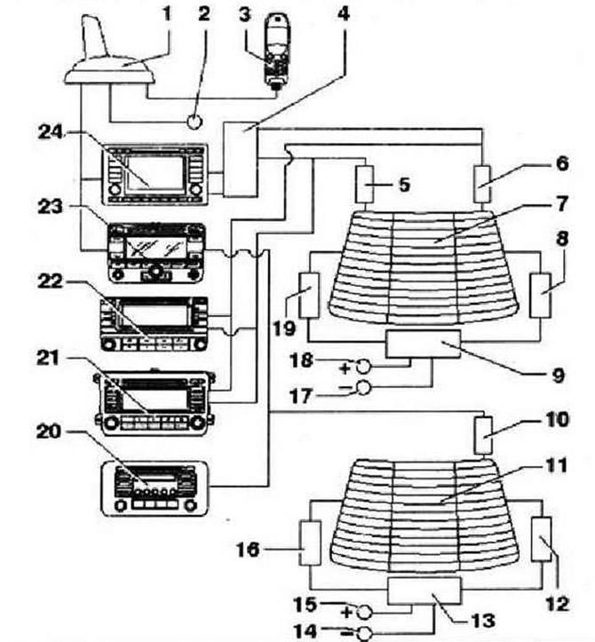
- 1 - Antenna -R11 roof antenna for operation of the navigation system, telephone and auxiliary heater remote control, located on the back of the roof
- 2 - Antenna connector for auxiliary heater remote control
- 3 - Mobile phone socket -R54-
- 4 - Aerial selection control unit -J515-, only installed in conjunction with radio and navigation display control unit -J503- RNS MFD 2 with CD drive
- 5 - Aerial amplifier -R24-, FM signal
- 6 - Aerial amplifier 2 -R111-, FM and AM signals
- 7 - Rear window with two antenna connectors, for receiving radio signals in the FM and AM bands
- 8 - Frequency filter for frequency modulation (FM) in the positive wire -R179-, in the wiring harness, its function is to prevent the transmission of the antenna signal to ground
- 9 - Frequency filter for amplitude modulation (AM) -R177-, integrated in the rear window, its function is to prevent the transmission of the antenna signal to ground
- 10 - Aerial amplifier 2 -R111- FM and AM signals
- 11 - Rear window with one antenna connector, for receiving a radio signal in the FM and AM bands
- 12 - Frequency filter for frequency modulation (FM) in the positive wire -R179-, in the wiring harness, its function is to prevent the transmission of the antenna signal to ground
- 13 - Frequency filter for amplitude modulation (AM) -R177-, integrated in the rear window, its function is to prevent the transmission of the antenna signal to ground
- 14 - Power supply of the rear window heating element, minus
- 15 - Power supply for the rear window heating element, plus
- 16 - Frequency filter for frequency modulation (FM) in the negative wire -R178- in the wiring harness, its function is to prevent the transmission of the antenna signal to ground
- 17 - Power supply of the rear window heating element, minus
- 18 - Power supply for the rear window heating element, plus
- 19 - Frequency filter for frequency modulation (FM) in the negative wire -R178- in the wiring harness, its function is to prevent the transmission of the antenna signal to ground
- 20 - Radio -R-, RCD, with a single antenna cable for radio reception in the FM/AM bands, no antenna diversity function
- 21 - Radio -R-, RCD 500, two aerial cables for AM/FM, aerial diversity integrated in the radio
- 22 - Radio -R-, RCD 300, two aerial cables for AM/FM, aerial diversity integrated in the radio
- 23 - Control unit with display for radio navigation system -J503-, radio navigation system RNS 300, with single antenna cable for FM/AM radio reception, no antenna separation function, with one antenna cable for signal transmission to the navigation system (roof antenna cable)
- 24 - Control unit with display for radio navigation system -J503-, radio navigation system RNS 510 with DVD drive
Components of antenna system for vehicles with digital satellite radio tuner (vehicles for USA and Canada)
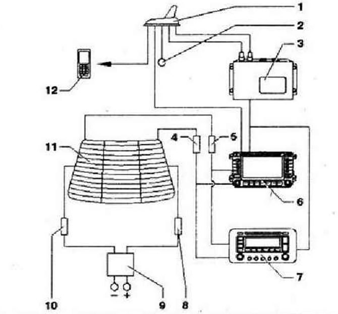
- 1 - Satellite tuner aerial -R172-, located at the rear of the roof, which, depending on equipment, is responsible for receiving signals for the operation of the navigation system, telephone, satellite radio and auxiliary heater remote control, From 11.06 there is only one aerial cable between the digital satellite radio and its aerial
- 2 - Antenna cable for auxiliary heater remote control (Telestart)
- 3 - Digital satellite radio -R190-, under front right seat. From 11.06 only one antenna cable between the digital satellite radio tuner and its antenna
- 4 - Aerial amplifier -R24-, FM signal
- 5 - Aerial amplifier 2 -R111-, FM/AM signals
- 6 - Control unit with display for radio navigation system -J503-, here RNS 510
- 7 - Radio -R-, here Premium Sound System
- 8 - Frequency filter for frequency modulation (FM) in the positive wire -R179-, in the wiring harness, its function is to prevent the transmission of the antenna signal to ground
- 9 - Frequency filter for amplitude modulation (AM) -R177-, in the tailgate in the middle, its function is to prevent the transmission of the antenna signal to ground
- 10 - Frequency filter for frequency modulation (FM) in the negative wire -R178- in the wiring harness, its function is to prevent the transmission of the antenna signal to ground
- 11 - Rear window aerial -R130-
- 12 - Telephony system
Removing and installing a frequency filter for amplitude modulation (AM)
In the Tiguan car, a frequency filter for amplitude modulation (AM) installed on the left side of the tailgate. Its task is to prevent the transmission of the antenna signal to ground. Switch off the ignition and all electrical consumers, remove the ignition key. To remove the frequency filter, you must first remove the tailgate trim. Remove securing screws -arrows-.
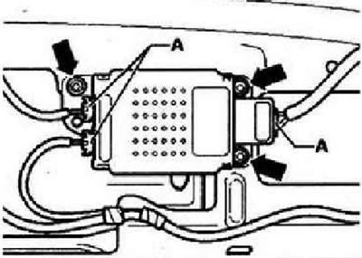
Unlock and disconnect connectors. To do this, first remove the latch -A- from each connector and then unlock the connector. Remove the frequency filter.
Removal and installation of the antenna selection control unit
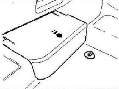
Switch off the ignition and all electrical consumers, remove the ignition key. Move the right front seat back as far as it will go. Detach cover under seat in -direction of arrow-.
Unlock and disconnect connectors -A-.
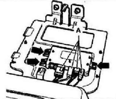
Remove clips -arrows- and remove control unit.
Roof antenna
Instructions: Vehicles for the USA and Canada are equipped with the following versions of the roof antenna: navigation system only, telephone only, satellite radio only, or navigation system, telephone and satellite radio. There are different versions of the roof aerial: only for the navigation system, only for the phone, for the navigation system and the phone, or for the navigation system, the phone and the auxiliary heater remote control. Rooftop antenna can be in the form of a plug, shark fin or 16-V antenna (pin). The following is a description of the operation of the shark fin antenna (pin) performed in a similar way.
Remove ceiling lining. Loosen nut -2-.
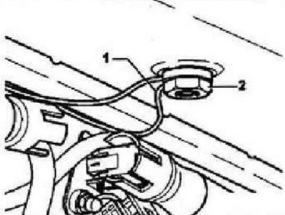
Unlock connectors -arrows-, disconnect and remove aerial.
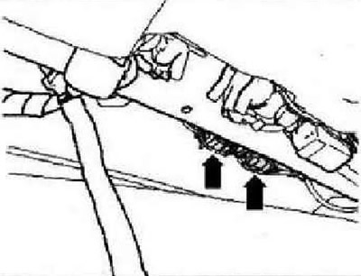
Instruction: Depending on the version of the antenna, there may be more connectors (up track). The phone cable connector has a purple casing. The navigation system cable connector has a blue casing. A third connector for the auxiliary heater remote control can also be installed.
Installation is carried out in the reverse order!
Instruction: When installing the antenna on the roof, make sure that the seal fits perfectly. Both seal guides must fit into the holes provided for them -ancestors- in the base of the antenna
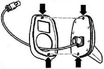
When installing the antenna, the cables -1- must be routed correctly through the special hole in the fixing nut -2-.

Visitor comments