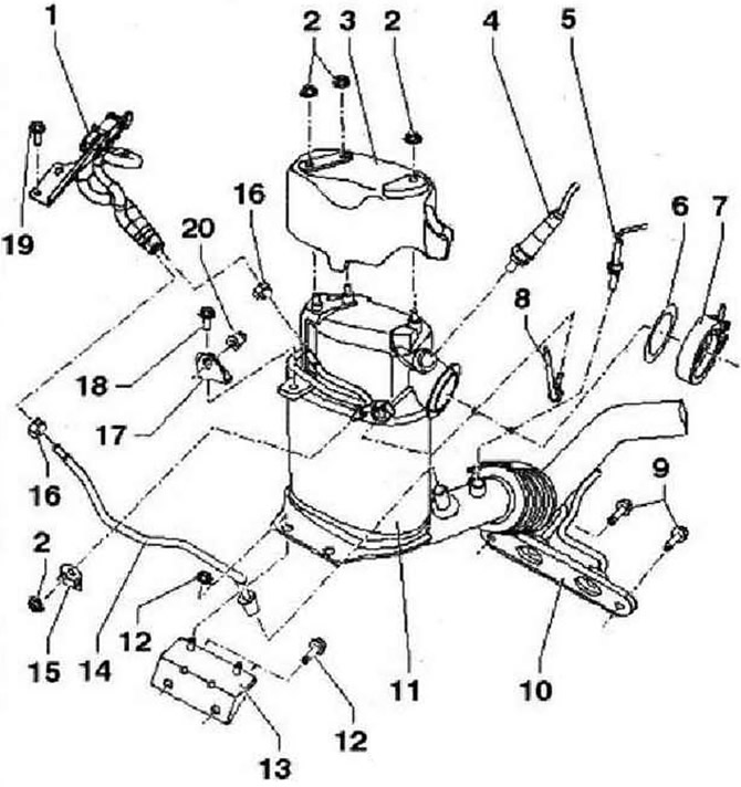
Instruction: After installing the elements of the exhaust system, it is necessary to check the absence of internal stresses in the system, as well as the presence of a sufficient distance between the elements of the system and the body. If necessary, loosen the double clamp and align the exhaust pipe and muffler so that there is sufficient clearance from the body and the fasteners are evenly loaded. Replace self-locking nuts. The split element for the front part of the exhaust system is secured with a transport protection -T10404- against rotation. When replacing the particulate filter or the exhaust gas pressure sender 1-G450-, it is absolutely necessary to adapt the exhaust gas pressure sender 1-G450- via tester: Guided functions: adaptation of the exhaust gas pressure sender 1-G450-.

- 1 - Exhaust pressure sensor 1-G450-
- 2 - 10 Nm
- 3 - Screen
- 4 - Lambda probe -G39-, 50 Nm. Lubricate only the threads with heat-resistant grease -G 052 112 AZ-, heat-resistant grease -G 052112 AZ- must not get into the slots of the probe body, for removal use lambda probe spanners -3337-
- 5 - Flue gas temperature sender 4 -G648-, 45 Nm, apply heat-resistant paste -G 052 112 33- to sensor thread
- 6 - Gasket, replace, observe installation position
- 7 - Clamp, 7 Nm
- 8 - Flue gas temperature sender 3 -G495-, 45 Nm, apply heat-resistant paste -G 052112 AZ- to sensor thread
- 9 - 25 Nm
- 10 - Suspension, replace if damaged
- 11 - Diesel particulate filter with oxidation catalyst and exhaust pipe, after replacement, install the soot mass balance adaptation using a tester on "0" in mode "Guided Functions".
- 12 - 25 Nm
- 13 - Bracket, screwed to the cylinder block
- 14 - Piping controls, 45 Nm
- 15 - Bracket, screwed to the particulate filter
- 16 - Clamp, replace
- 17 - Bracket, screwed to the cylinder block
- 18 - 25 Nm
- 19 - 8 Nm
- 20 - 25 Nm
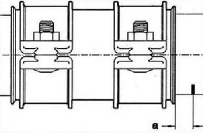
Mounting position of the connecting sleeve

Install a double clamp at a distance -a- = 5 mm from the mark on the exhaust pipe of the diesel particulate filter.

Visitor comments