Poly V-belt storage
Caution: Before installing the V-ribbed belt, check that all the components driven by it are securely fastened (generator, air conditioner compressor). When installing the V-ribbed belt, pay attention to the direction of travel and the correct fit on the pulleys and tensioning elements.
First put the V-ribbed belt on the crankshaft pulley. The belt is put on the tension roller last. Further installation is carried out in the reverse order. Fill with coolant. After completion of work. Start the engine and check the drive belt.
Belt drive with air conditioner compressor
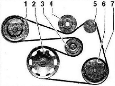
- 1 - Belt pulley - coolant pump
- 2 - Belt pulley - crankshaft
- 3 - Tension roller
- 4 - Tension roller
- 5 - Belt pulley - generator
- 6 - Belt pulley - air conditioner compressor
- 7 - V-ribbed belt
Belt drive compressor
Note: The belt pulley for the magnetic clutch of the compressor -N421- is located behind the belt pulley - coolant pump. The V-ribbed belt -4- passes through the belt pulley of the electromagnetic compressor clutch -N421-.
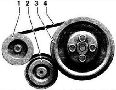
- 1 - Belt pulley - compressor
- 2 - Tension roller
- 3 - Belt pulley for coolant pump with belt pulley for electromagnetic compressor clutch -N421-
- 4 - V-ribbed belt
Removing and installing engine speed sender -G28-
The fitting location for the engine speed sender -G28- is on the crankshaft sealing flange on the flywheel side. Remove compressor. Unplug connector -1- for engine speed sender -G28-.
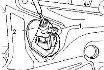
Remove seal -2- from cylinder block and remove engine speed sender -G28- using socket wrench -T10370-.
Installation
Install engine speed sender -G28- and tighten screw to 5 Nm. Further installation is carried out in the reverse order.
Cylinder head
Instruction: When installing an exchange cylinder head, before installing the camshaft housing, it is necessary to lubricate with engine oil all contact surfaces between the bearing elements, roller levers and the camshaft bed. Remove the plastic pads protecting the open valves only immediately before installing the MCC. When replacing the cylinder head, you should also drain the old and fill in new coolant. Lubricate all support and work surfaces before assembly work.
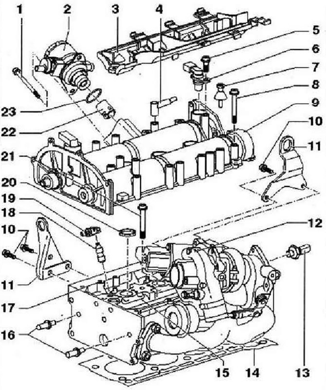
- 1 - 20 Nm
- 2 - Injection pump for fuel system, with fuel pressure regulating valve -N276-
- 3 - Wiring, fasten to the camshaft housing with a torque of 8 Nm
- 4 - To the air filter
- 5 - 10 Nm
- 6 - Hall sender -G40- with lip seal, replace seal if damaged
- 7 - Studs, 6 Nm
- 8 - 10 Nm and tighten by 90°, replace, tighten from center to edges
- 9 - Camshaft housing. Make sure that the oil circuit mesh must be installed in the cylinder head. Remove the remnants of the old sealant, carefully clean the seating surfaces; they must be free of oil and grease, coat with sealant -D 188 003 A1- before installation, install vertically from above on studs and pins
- 10 - 20 Nm
- 11 - Hanging eye
- 12 - Turbocharger
- 13 - Oil pressure switch -F1-, 25 Nm, cut sealing ring if leaks and replace
- 14 - Cylinder head gasket, replace, metal. After replacement, change the coolant
- 15 - Cylinder head. Make sure that the oil circuit mesh must be installed in the cylinder head. The sealing surfaces to the camshaft housing must be free of oil and grease; after replacement, change the coolant
- 16 - Guide pins, 20 Nm
- 17 - Locating pin
- 18 - Supporting element, do not interchange, with hydraulic valve clearance compensation, lubricate the working surface
- 19 - Roller valve lever (rocker), weld the roller bearing for jamming, lubricate the working surface, fix it on the support with a locking clip when installing
- 20 - Sealing ring. When removing and installing the camshaft bearing housing, different seals must be taken into account, replace, 4 pieces, insert into the cylinder head
- 21 - Cylinder head bolt, replace. Observe the assembly instructions and sequence when loosening and tightening
- 22 - Roller tappet, lightly lubricate the working surfaces with engine oil
- 23 - O-ring, replace, moisten with engine oil before replacing
Checking the cylinder head for warping
The maximum allowable curvature of the contact plane: 0.05 mm.
Removing the camshaft drive chain and oil pump drive chain
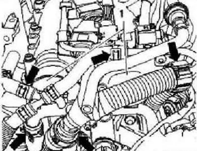
Raise engine cover at points -1- and remove engine cover by moving forward in direction of arrow-. Remove air filter. Drain coolant. Remove coolant hoses and guides -arrows-.
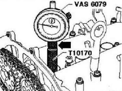
Unscrew the mounting bolts and remove the camshaft plugs. Remove the spark plug of the first cylinder. Use puller -T10094 A- and spark plug wrench -3122 B-. Screw adapter for dial indicator -T10170- into spark plug socket as far as it will go. Insert dial gauge -VAS 6079- with extension -T10170/1- as far as it will go and press down with nut -arrow-,
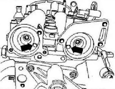
Rotate the crankshaft in the direction of engine rotation to the TDC of cylinder 1. Note the position of the small hand on the dial gauge. The holes -arrows- on the distribution lugs must be positioned as shown. Turn the crankshaft one more turn if necessary (360°).
Instruction: If the crankshaft was rotated beyond TDC by more than 0.01 mm, then it should be turned again against the direction of engine rotation by about 45°Finally, bring the crankshaft in the direction of engine rotation to the TDC of cylinder 1. Permissible deviation from TDC of the first cylinder:±0.01 mm.
Insert camshaft clamp -T10171 A- into camshaft bore as far as it will go. Locking pins -arrows 1- must engage in holes -arrows 2-. mark "TOR"-with heating pad 3- must be visible from above.
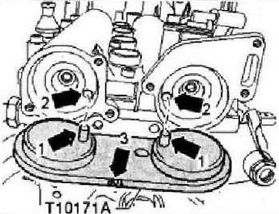
To secure the camshaft clamp -T10171 A-, screw in the M6 bolt and the appropriate hole -arrows- by hand; do not tighten.
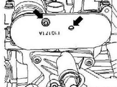
Note: Note that the camshaft clamp -T10171A- has different attachment points.
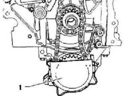
Remove timing case. Remove cover -1- from oil pump sprocket.
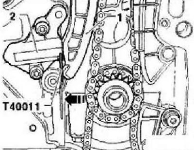
Press tensioning bar by hand in -direction of arrow- and secure tensioner piston with pins -T40Q11-.
Mark the direction of the timing target with a felt-tip pen -3-.
Instruction: The phase shifter mounting bolt -2- has a left-hand thread.
Remove bolts -2- and -4- and remove camshaft adjuster -1- with timing chain -3-. In doing so, use support -T10172- to secure it.
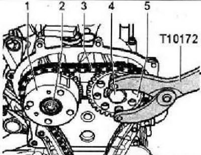
Support oil pump sprocket with support -T10172- and remove securing bolt -1-.
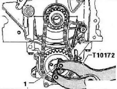
Press tensioning spring -1- on bolt -2- with a screwdriver and remove spring -1-. Remove securing bolt -3- and remove chain tensioner. Mark the running direction of the oil pump drive chain -2- with a felt-tip pen.
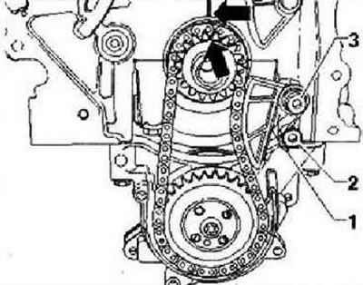
Unscrew bolt for sprocket -1- and remove sprockets -1- and -3- together with oil pump drive chain -2-.
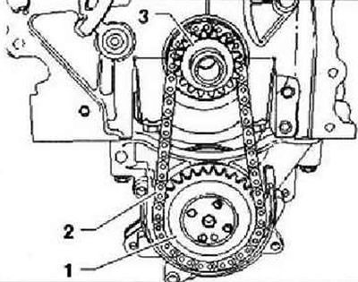
Installation
The crankshaft must be at TDC of the first cylinder. Fit sprocket -1- in -direction of arrow- to stop on crankshaft journal.
Caution: The cast lug -2- of the sprocket must fit into the groove -3- on the crankshaft journal.
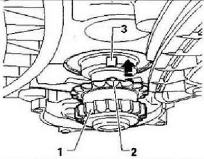
Mark the positions of the sprocket and crankshaft relative to the cylinder block with a felt-tip pen.
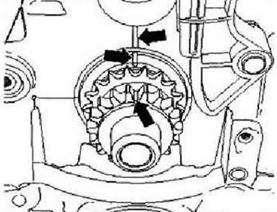
Lay oil pump drive chain -3- on sprocket -1- and at the same time fit sprocket -2- on oil pump drive shaft.
Note: Pay attention to the marking for the direction of travel on the oil pump timing chain. The oil pump gear is only aligned to the position on the oil pump drive shaft -arrow-.
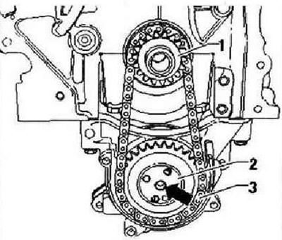
Support oil pump drive gear -T10172-. Tighten new securing bolt -1- to 20 Nm and turn 90°further. Install the tensioner on the oil pump drive chain and tighten the mounting bolt -3- to a torque of 15 Nm. Depress tension spring -1- with a screwdriver, leaning on bolt -2-.
Instructions: Pay attention to the marks -arrows-. Do not turn the crankshaft.
Secure sprocket -3- by hand with a new bolt. Lay timing chain -1- on crankshaft sprocket -4-, exhaust camshaft sprocket -3- and screw in camshaft adjuster -2- by hand with a new fixing bolt.
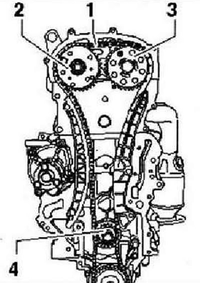
Instruction: Pay attention to the marking for the direction of travel on the camshaft timing chain. Check the installation of the centering sleeve between the intake camshaft and the camshaft adjuster. The phase shifter mounting bolt -2- has a left-hand thread.
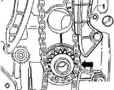
The camshaft drive chain must rest on the chain guide -1- and rest on the camshaft sprocket -arrow-.
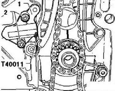
Fit target tensioner -1- and tighten screws -2- to 9 Nm. Tension the timing chain by pulling out the locking pin -T40011- from the chain tensioner. Check the location of the marks on the crankshaft gear and cylinder block, they should be opposite each other.
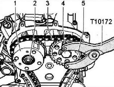
Tighten bolt -2- to 40 Nm and bolt -4- to 50 Nm (use stop -T10172-).
Instruction: Only tighten bolts -2- and -4- by 90°after the valve timing has been checked. The phase shifter mounting bolt -2- has a left-hand thread.
Unscrew bolt -arrow- and remove retainer -T10171 A- from camshaft housing. Check valve timing. If the valve timing is ok. Support camshaft sprockets with support -T10172- and tighten bolts -2- (left hand thread) and -4- with a 90°hard wrench.
Instruction: The phase shifter mounting bolt -2- has a left-hand thread. When tightening the bolts, the sprockets must not rotate on the camshafts.
Install oil pump gear cover -1-. Install the timing case. Install the crankshaft pulley. Install poly V-belt. Press engine cover at points -1- in direction of -arrow- downwards until it locks into place. Further installation is carried out in the reverse order.

Visitor comments