ATTENTION: Switchable stabilizers must be switched on before starting work. Otherwise, unintentional activation of the stabilizers may result in injury.
Switch on the hydraulic system in non-pressure mode.
Remove the bottom noise screen.
Disconnect both hydraulic lines 1 and electrical connection 2 (rice. 4.54).
When installing, do not confuse the pipelines.
Check if there is a mark on the front «in the direction of travel» pipeline. If it doesn't exist, apply a new one.
When unscrewing the pipelines, hold them with an open-end wrench.
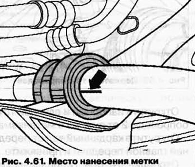
Remove the stabilizer clamps and mark the mounting position of the stabilizer bearings on them (pic. 4.61).

Disconnect the stabilizer from the connecting rods.
Installation of a switchable stabilizer.
Installation is carried out in the reverse order.
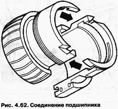
Install the bearing halves on the stabilizer (pic. 4.62).

In doing so, pay attention to the following.
Marks applied to the stabilizer when removed.
the larger outer diameter of the bearing halves should point outward.
After installation, the hydraulic system must be bled.
When tightening, hold the hexagon of the union nut.
Install the front noise screen.
Tightening torques
| Component | Torque. Nm |
| Connecting rod to stabilizer | 110 |
| Stabilizer to subframe | 60 |
| Connection of hydraulic pipelines | 15 |

Visitor comments