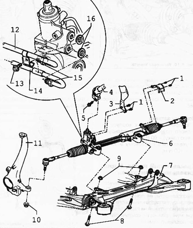
Pic. 5.11. Steering Gear Components:
1 - a bolt with a six-sided head; 2 - screen; 3 - screen; 4 - universal joint; 5 - a bolt with a six-sided head; 6 - steering mechanism with an amplifier; 7 - subframe; 8 - a bolt with a six-sided head; 9 - self-locking nut; 10 - self-locking nut; 11 - wheel bearing housing; 12 - pressure pipeline; 13 - a bolt with a six-sided head; 14 - return line; 15 - cap bolt, 30 Nm; 16 - sealing ring.
Removing
ATTENTION: Switchable stabilizers must be switched on before starting work. Otherwise, unintentional activation of the stabilizers may result in injury.
Remove wheels.
Clamp the supply and drain lines with hose clamps.
Press the tie rods out of the wheel bearing housing.
Unscrew the left tip from the steering rod.
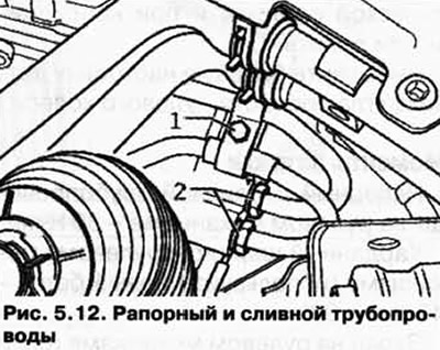
Unscrew the holder for the hydraulic lines 1.
Unscrew the pressure and drain pipes 2 from the steering gear (pic. 5.12).

Turn the steering mechanism to the left until it stops.
If equipped, remove the screen from the steering gear (2 bolts).
Unscrew the bolt of the universal joint of the steering gear and remove the joint from the steering gear.
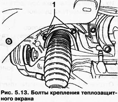
Unscrew heat shield 1 (pic. 5.13).

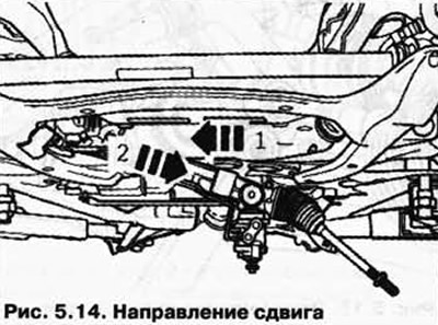
Move the steering gear to the right side of the car (pic. 5.14).

Rotate the left tie rod down.
After that, remove the steering gear towards the left side of the car and down.
Installation
Installation is carried out in the reverse order, paying attention to the following.
Bleed the steering system.
Check the steering system for leaks.
Check the hydraulic oil level and top up if necessary.
Carry out the basic setting of the steering angle sensor.
Tightening torques
Pressure and drain pipelines on the steering gear - 30 Nm.
Cardan joint to steering gear (use new bolt) - 40 Nm + 90°.
Screen on steering gear (if available) - 10 Nm.
Wishbone to wheel bearing housing (use a new nut) - 90 Nm.

Visitor comments