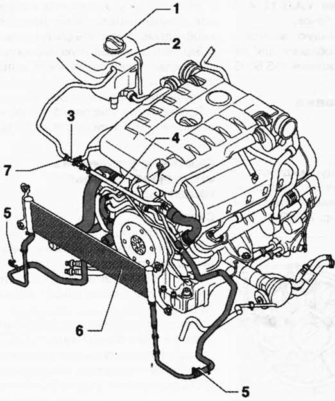
Pic. 2.240. Body-mounted cooling system components:
1 - cover; 2 - expansion cans; 3 - tee; 4 - coolant hose; 5 - holder; 6 - radiator.
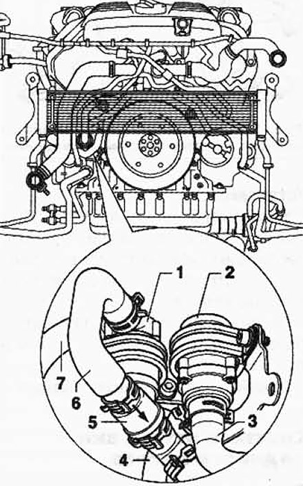
Installation location of the coolant overrun pump and fuel cooling system pump.

Pic. 2.241. Installation location of the coolant overrun pump and fuel cooling system pump:
1 - coolant run-out pump V51; 2 - fuel cooling system pump V166; 3 - to the pump of the fuel cooling system V166; 4 - from the pump of the fuel cooling system V166; 5 - check valve 6 - from the coolant run-out pump V51; 7 - to the coolant circulation pump V51.
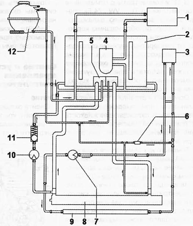
Scheme of connecting the hoses of the engine cooling system (vehicles with BLE and BWF engines).

Pic. 2.242. Scheme of connecting the hoses of the engine cooling system (vehicles with BLE and BWF engines):
1 - heat exchanger; 2 - cylinder head / cylinder block; 3 - fuel cooler; 4 - radiator; 5 - thermostat housing; 6 - valve stem; 7 - pump of the fuel cooling system V166; 8 - radiator; 9 - radiator; 10 - coolant run-out pump V51; 11 - check valve; 12 - expansion tank.

Visitor comments