WARNING: When opening the expansion tank, hot steam may come out. to avoid eye injury and scalding, wear protective goggles and protective clothing. Cover the bull's lid with a rag and carefully open it.
ATTENTION: For any assembly work, in particular in the engine compartment due to the dense layout, the following must be taken into account. Highways of all types (e.g. fuel, hydraulic, activated charcoal absorber, cooling systems, air conditioning circuits, brake lines, vacuum hoses), as well as electrical wires must be laid as they were originally laid.
Provide free space for all moving and hot components.
NOTE: Hose connections are secured with spring clamps. When repairing, use only spring clamps.
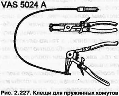
We recommend using spring clamp pliers VAS 5024 A for mounting spring clamps (pic. 2.227).
When installing, route the cooling system hoses by pulling on them. Make sure they don't touch other components (observe the markings on the radiator pipe and hose).
Elements of the cooling system installed on the body
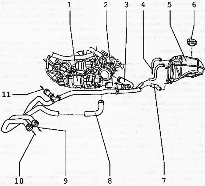
Pic. 2.228. Elements of the cooling system installed on the body:
1 - coolant circulation pump V51; 2 - coolant hose; 3 - coolant hose; 4 - from the radiator; 5 - expansion tank; 6 - cover; 7 - coolant hose; 8 - coolant hose; 9 - to the heater heat exchanger; 10 - from the heat exchanger of the heating system; 11 - to the thermostat housing.
ATTENTION: For any assembly work, in particular in the engine compartment due to the dense layout, the following must be taken into account. Highways of all types (e.g. fuel, hydraulic, activated charcoal absorber, cooling systems, air conditioning circuits, brake lines, vacuum hoses), as well as electrical wires must be laid as they were originally laid. Particularly when laying the cooling system hoses, and in order to avoid damage, attention must be paid to the presence of sufficient space between the hoses themselves, as well as with all moving or hot elements.
Installation location of the coolant afterrun pump V51
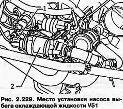
The coolant circulation pump V51 2 is attached behind the cylinder head under the solenoid valve 1 of the activated charcoal filter N80 with damping rings to the bracket.
Thermostat housing
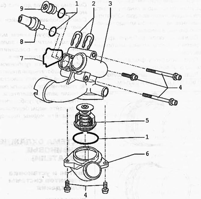
Pic. 2.230. Thermostat body mounting diagram:
1 - O-ring; 2 - mounting bracket; 3 - thermostat housing; 4 - bolt 8 Nm; 5 - thermostat; 6 - connecting pipe; 7 - sealing ring; 8 - coolant temperature sensor G62; 9 - cork.
ATTENTION: For any assembly work, in particular in the engine compartment due to the dense layout, the following must be taken into account. Highways of all types (e.g. fuel, hydraulic, activated charcoal absorber, cooling systems, air conditioning circuits, brake lines, vacuum hoses), as well as electrical wires must be laid as they were originally laid.
Provide free space for all moving and hot components.
Connection plan for cooling system hoses
The scheme of connection of hoses of system of cooling is shown in fig. 2.231.
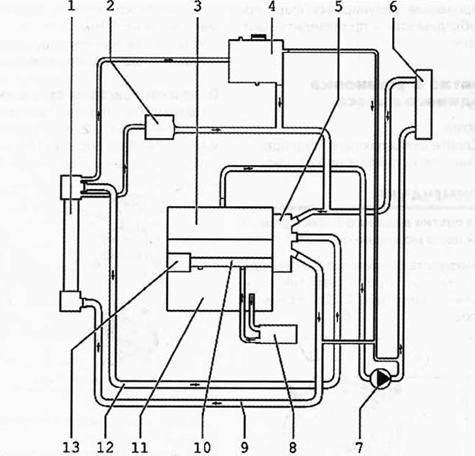
Pic. 2.231. Cooling system hose connection diagram:
1 - radiator; 2 - oil cooler; 3 - cylinder head; 4 - expansion tank; 5 - thermostat housing; 6 - heat exchanger of the heating system; 7 - coolant circulation pump V51; 8 - oil cooler; 9 - coolant hose, top; 10 - coolant supply pipe; 11 - cylinder block; 12 - coolant hose, lower; 13 - water pump.

Visitor comments