NOTE: The engine is removed with the gearbox down.
WARNING: The fuel line is under pressure. Wear safety goggles and gloves to avoid injury and skin contact. Wrap a rag around the connection before disconnecting the hoses. Then release the pressure by gently loosening the connections.
Preliminary actions
To ensure unimpeded scrolling of the cardan shaft, set the selector lever to the position «N».
Leave the key in the ignition to prevent the steering from locking.
Before starting the dismantling of the power unit, it is recommended to remove the front wheels. Due to this, the car can be lowered on the lift, leaving a few centimeters between the casings of the brake discs and the floor. Thus, during operation, optimal reach of all components in the engine compartment will be ensured.
To avoid damage to the removed parts, use the VAG 1698 removed parts container.
Some components in this vehicle cannot be or are difficult to remove without removing the engine. Therefore, before removing the engine, it is necessary to identify all defective parts and replace them after removing the engine.
Switch off the ignition and all electrical consumers.
Disconnect the battery under the driver's seat.
Removing the power unit with gearbox assembly
Remove the left and right wiper arms. Remove the hood seal from the front wall.
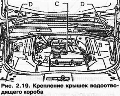
Remove covers A, B and C in the engine compartment and D of the plenum box (pic. 2.19).
Screw adapter VAG 1318/ 20-1 to adapter VAG 1318/ 20 (pic. 2.20).
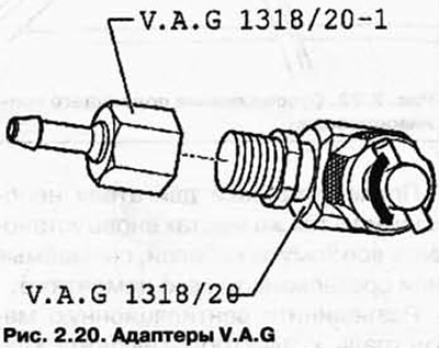
turn the valve (on T-adapter) counterclockwise and open it fully.
CAUTION: Before depressurizing the fuel system, connect the evacuation tool V4S 5226 and relieve pressure.
Unscrew the air valve cover.
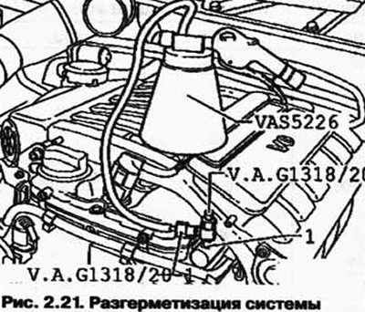
Connect adapter VAG 1318/20 to air valve 1 with adapter VAG 1318/20-1 and extraction device VAS 5226.
Screw in the valve (on T-adapter) clockwise until it stops at the air valve (pic. 2.21).
After the fuel pressure has been released, the fuel system can be depressurized.
Place an additional rag under the joint to absorb escaping fuel.
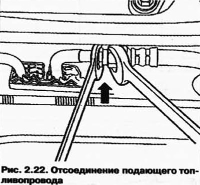
Disconnect the fuel supply line (pic. 2.22).
After installing the engine, it is necessary to reinstall all cable ties that are removed or cut off during its dismantling in the same places.
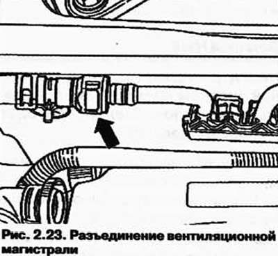
Disconnect the ventilation line to the N80 absorber solenoid valve 1 in the engine compartment (pic. 2.23).
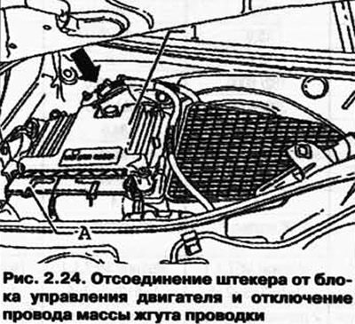
Disconnect the small plug A from the engine control unit and disconnect the ground wires of the wiring harness (pic. 2.24).
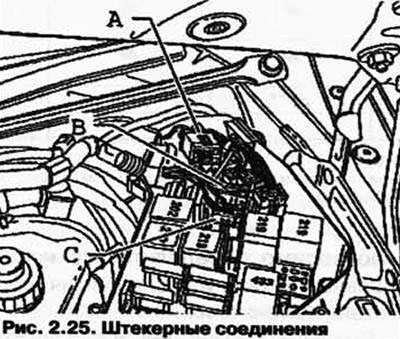
Open the cover of the fuse box, on the left in the plenum chamber and disconnect the plug connections A, B and C (pic. 2.25).
Remove the wiring harness from the plenum box and place it on the engine.
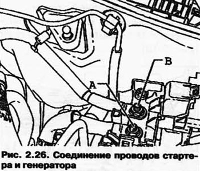
Disconnect starter A and alternator B wires and put them on the engine (pic. 2.26).
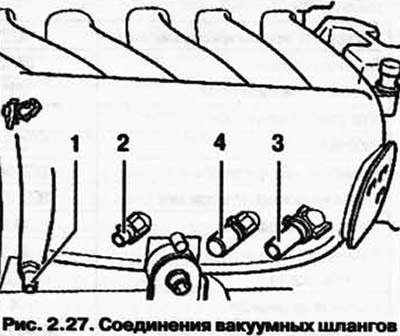
Disconnect the vacuum hoses 1-3 from the intake manifold.
On vehicles with engine code BAA, additionally remove vacuum hose 4 from the intake manifold (pic. 2.27).
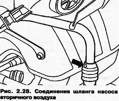
Disconnect the hose from the secondary air pump (pic. 2.28).
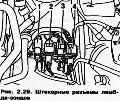
Disconnect plugs 1-4 lambda probes and put the plugs on the engine (pic. 2.29).
Cylinders 1-3: black.
Cylinders 4-6: brown.
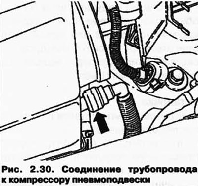
Disconnect the pipe to the air suspension compressor from the air filter (arrow in figure 2.30) in the manner described below.
Carefully pry off the green retaining ring with 1 screwdriver. Then press on the clamping ring 2 in the direction of the arrow in Figure 2.31.
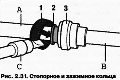
After that, disconnect the weakened line B from the branch pipe A on the air filter.
Pull the top of the air filter up. Unblock and disconnect the pipeline of ventilation of a crankcase of a transmission from the case of the air filter.
Extract the refrigerant from the air conditioner.
WARNING: When opening the expansion tank, hot steam may come out. to avoid eye injury and scalding, wear protective goggles and protective clothing. Cover the bull cover with a rag and carefully unscrew it.
Drain the coolant. Disconnect the upper hose from the radiator and the lower hose from the radiator tube.
Disconnect tubes (arrow in figure 2.32) from the transmission oil cooler, bottom right. Place a container under the leaking oil.
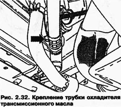
Then disconnect the piping from the hydraulic oil cooler at the bottom left. Place a container under the leaking oil.
Release the double clamp between the catalytic converter and the intermediate muffler, and then slide the clamp forward.
Support the main muffler on the rack for the engine and gearbox VAG 1383A, unscrew the suspension fasteners of the rear of the exhaust system and lower it.
Remove the heat shield on the steering gear and loosen the universal joint.
Disconnect the connectors A on the gearbox and transfer case B and unhook the selector rod (pic. 2.33).
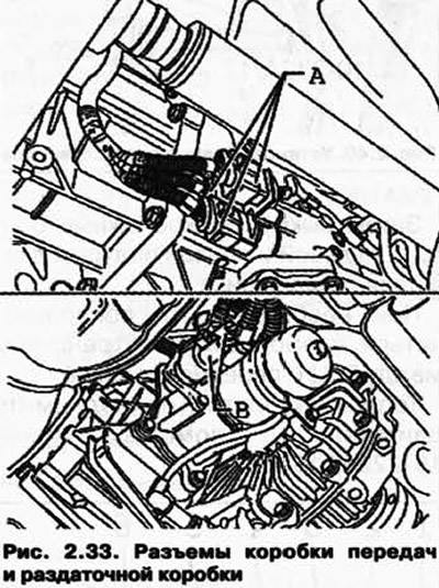
Remove the rear driveshaft. Remove the front wheels.
Remove the front fenders. Disconnect the brake pipes from the brake hose in the wheel housing and collect the escaping brake fluid. Disconnect all plug connections between the body and the front axle in the wheel arches.
Remove the air suspension pipes from the shock absorber strut.
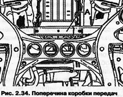
Remove the transaxle A (pic. 2.34).
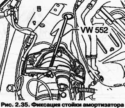
Fix the shock absorber struts as shown in Figure 2.35 using the VW 552 spring clamp.
Loosen the upper bolts on each side of the car on the shock absorber struts. Install the mounting table for further work on removing the engine.
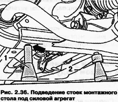
Position a horizontally leveled mount table under the power unit. Supports 1 must be inserted into the corresponding slots on the left and right (pic. 2.36).
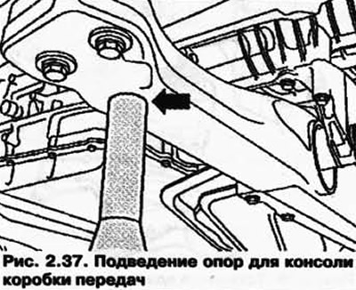
Simultaneously insert the right and left supports for the transmission console into the corresponding hole (pic. 2.37).
When all four supports are fixed in the receiving holes without pressure, unscrew both plates of conductors with a slight tension under the suspension arms so that the spring clamp VW 552 suspended for insurance can be removed.
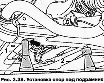
Insert the supports 2 into the respective sockets in the subframe, if necessary, adjust the height of the supports using the knurled nut (pic. 2.38).
Unscrew the subframe bolts 1, 2 and 3, as well as the gearbox cross members 4.
NOTE: After removing the subframe, the wheel alignment must be adjusted.
Slowly lower the power unit down while continuously checking for a smooth ride.

Visitor comments