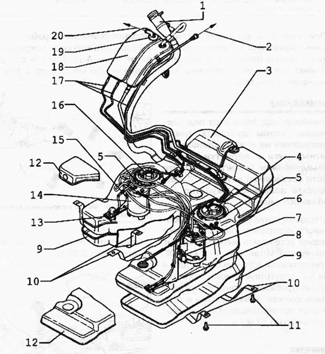
Pic. 2.306. Fuel system components:
1 - fuel tank neck; 2 - to the absorber with activated carbon; 3 - fuel tank; 4 - fuel filter; 5 - locking ring, 145 Nm; 6 - fuel supply module; 7 - fuel level sensor 3 G237; 8 - ejection pump; 9 - protective cover; 10 - bandage; 11-20 Nm + tighten 1/4 turn. (90°); 12 - protective cover; 13 - ejection pump; 14 - fuel supply module; 15 - fuel level indicator sensor G; 16 - flange; 17 - ventilation hose; 18 - expansion tank; 19 - gravity feed valve; 20 - to the pressure reducing valve.
WARNING: Observe the following instructions for any assembly work on the fuel tank. Lines of all kinds (e.g. fuel, activated charcoal canister, vacuum hoses), as well as electrical wires must be laid as they were originally laid. Check the strength of the ground wire between the fuel filler neck and the body to protect against electrostatic discharge. Provide free space for all moving and hot components.

Visitor comments